
Electric Guitar Preamplifier

The first section of the preamplifier circuit is a single-transistor common-emitter amplifier with degenerative feedback in the emitter and a boot-strapped bias divider to ensure optimal input impedance. With the specified component values, the input impedance exceeds 50 kilo-ohms, and the peak output voltage is approximately 2V RMS. The master-level-control potentiometer, VR1, should be adjusted to minimize distortion. The input from the guitar pickup connects to the preamplifier at terminal J1. The signal is buffered and processed by an operational amplifier circuit built around IC TL071 (IC1). The gain can be adjusted using the preset potentiometer, VR2. The circuit includes both a master and a slave control. RCA socket J2 serves as the master signal output, while socket J3 functions as the slave output. It is preferable to use the signal from J2 as the input to the power amplifier system or sound mixer, while output signals from J3 can drive a standard headphone amplifier. The slave output level at J3 can be adjusted using potentiometer VR3.
The entire circuit should be housed in a metallic case, with VR1 and VR3 ideally being types with metal enclosures to reduce interference. To mitigate hum, it is essential to ground both the case and the enclosures. A well-regulated 9V DC power supply is critical for the operation of this circuit, although a standard 9V alkaline manganese battery can also be utilized. The circuit includes a power on/off switch, denoted as S1.
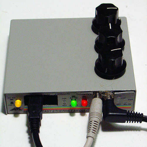
This guitar preamplifier circuit effectively amplifies the weak electrical signals generated by the pickups, ensuring high fidelity and low noise for subsequent audio processing. The use of a common-emitter amplifier configuration provides significant voltage gain, while the operational amplifier stage allows for flexible gain adjustment and buffering, maintaining signal integrity. The dual output configuration enhances versatility, accommodating different audio equipment setups. Proper grounding and shielding measures are integral to minimizing electromagnetic interference, ensuring optimal performance in various environments.Here is the circuit diagram of a guitar preamplifier that would accept any standard guitar pickup. It is also versatile in that it has two signal outputs. A typical example of using a pick-up attached to a guitar headstock is shown in Fig. 1. The pickup device has a transducer on one end and a jack on the other end. The jack can be plugged into a preamplifier circuit and then to a power amplifier system. The pickup device captures mechanical vibrations, usually from stringed instruments such as guitar or violin, and converts them into an electrical signal, which can then be amplified by an audio amplifier. It is most often mounted on the body of the instrument, but can also be attached to the bridge, neck, pick-guard or headstock.
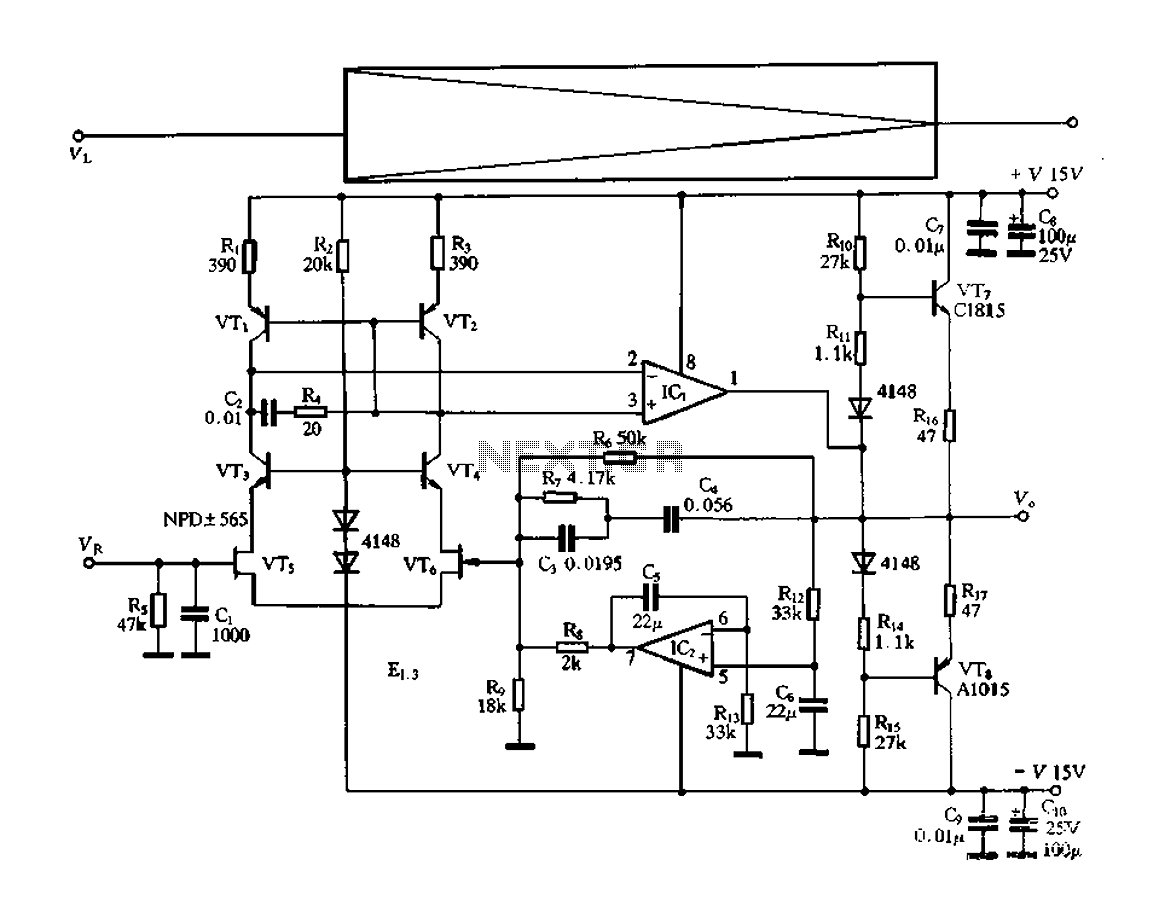
The first part of this preamplifier circuit shown in Fig. 2 is a single-transistor common-emitter amplifier with degenerative feedback in the emitter and a boot-strapped bias divider to secure optimal input impedance. With the component values shown here, the input impedance is above 50 kilo-ohms and the peak output voltage is about 2V RMS.
Master-level-control potentiometer VR1 should be adjusted for minimal distortion. The input from guitar pickup is fed to this preamplifier at J1 terminal. The signal is buffered and processed by the op-amp circuit wired around IC TL071 (IC1). Set the gain using preset VR2. The circuit has a master and a slave control. RCA socket J2 is the master signal output socket and socket J3 is the slave. It is much better to take the signal from J2 as the input to the power amplifier system or sound mixer. Output signals from J3 can be used to drive a standard headphone amplifier. Using potentiometer VR3, set the slave output signal level at J3. House the circuit in a metallic case. VR1 and VR3 should preferably be the types with metal enclosures. To prevent hum, ground the case and the enclosures. A well-regulated 9V DC power supply is crucial for this circuit. However, a standard 9V alkaline manganese battery can also be used to power the circuit. Switch S1 is a power on/off switch. 🔗 External reference
Related Circuits
This document serves as a compilation of design notes, providing practical details as construction progresses, along with some photographs that will be included in due course. Currently, it functions as a progress report, blending immediate plans with actual construction,...
The interest in tube circuits remains significant. Therefore, I will provide a comprehensive circuit of a preamplifier that is sufficiently detailed. It is primarily composed of the main preamplifier department, the input selector department, application voltage delay, and the connection...
Make your own Guitar Effects Pedal with an Arduino board. Bit crushing, rate reducing, weird noises. 10-bit effects/guitar pedal with an Arduino for lo-fi DSP The project involves designing a guitar effects pedal utilizing an Arduino microcontroller to create various...
The electronic switch functions as a multifunctional preamplifier. It features a five-way touch electronic switch, a high-speed DC servo RIAA ultralow distortion amplifier, and can control volume, tone, and power amplifier electrical path phase. The TC9152, shown in Figure...
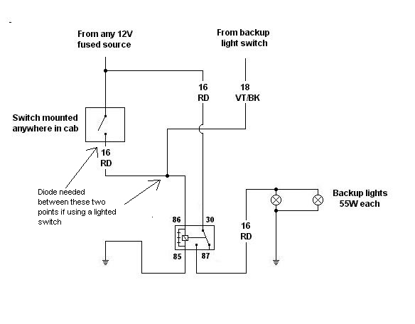
Utilizing a relay allows for a reduction in the length of thick wires that need to be routed, particularly through the firewall and beneath the dashboard. This approach also minimizes the necessity for a larger switch. However, when integrating...
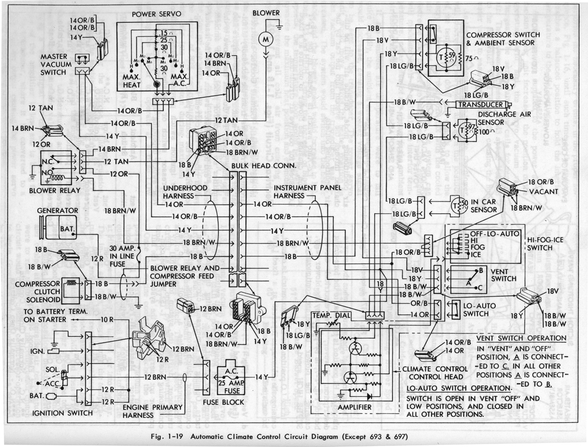
Gerald's 1958 Cadillac Eldorado Seville, 1967 Cadillac Deville, 1967 Eldorado, and 1971 Lincoln Continental Mark III - everything you always wanted to know about these cars. The 1958 Cadillac Eldorado Seville is a classic American luxury vehicle renowned for its...