
Motorola Hi-Fi power amplifiers

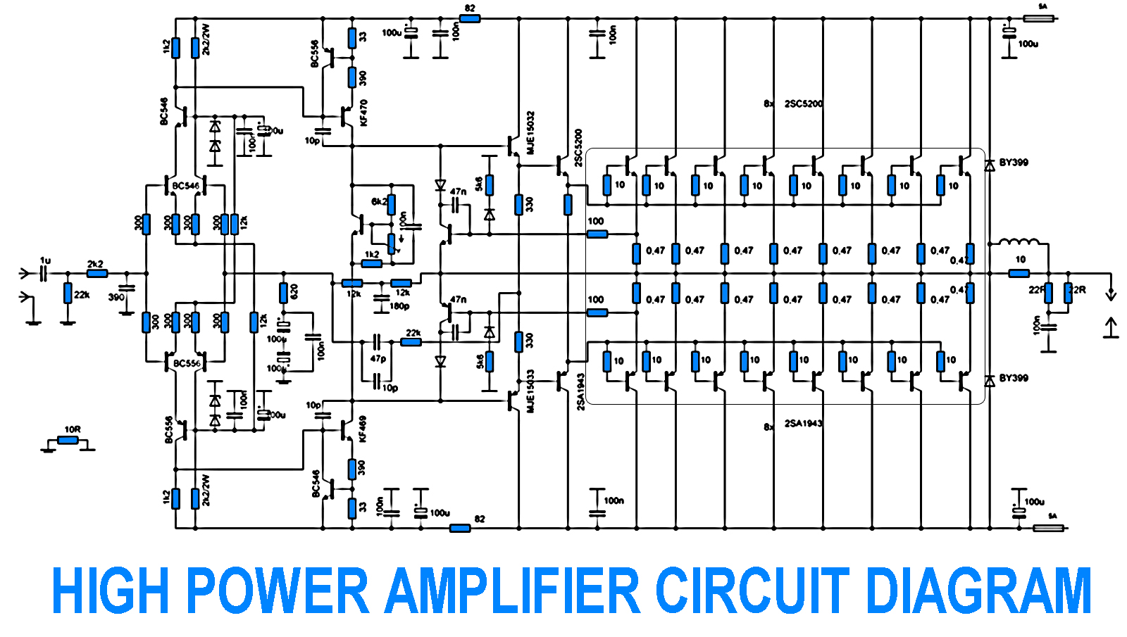
The Hi-Fi quality power amplifier circuit is designed to deliver high fidelity audio output while maintaining cost-effectiveness. The amplifier can be configured in five distinct ways to accommodate various power requirements, allowing for an output range from 20 watts to 80 watts RMS.
The core of the amplifier typically consists of a complementary push-pull output stage, which enhances efficiency and linearity, minimizing distortion while maximizing sound quality. The design may incorporate a voltage gain stage, often utilizing operational amplifiers or transistors, which can be adjusted based on the desired output power.
Input and output stages are crucial for the performance of the amplifier. The input stage may include capacitive coupling to block DC offset, ensuring only the AC audio signal is amplified. The output stage is designed to drive speakers effectively, with considerations for impedance matching to optimize power transfer and reduce signal loss.
Power supply requirements for this amplifier should be considered carefully. A regulated power supply may be necessary to ensure consistent performance and avoid fluctuations that could lead to distortion or clipping during high-demand audio peaks.
Thermal management is also an essential aspect of the design. Heatsinks may be employed to dissipate heat generated by the output transistors, ensuring reliable operation over extended periods.
Overall, this amplifier circuit not only provides versatility in output power configurations but also emphasizes high-quality sound reproduction, making it suitable for various audio applications, from home audio systems to small public address systems. Properly implemented, this design can deliver impressive audio performance while remaining accessible to hobbyists and professionals alike.This is a very simple, low cost, Hi-Fi quality power amplifier. You can build it 5 ways, like it?s shown in the table (from 20 W to 80 W RMS).. 🔗 External reference
Related Circuits
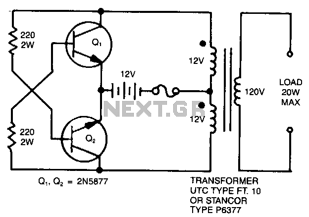
A simple 120 V to 24 V center-tapped control transformer, along with four additional components, can accomplish the task. This circuit produces a clean 200 V peak-to-peak square wave at 60 Hz and is capable of supplying up to...
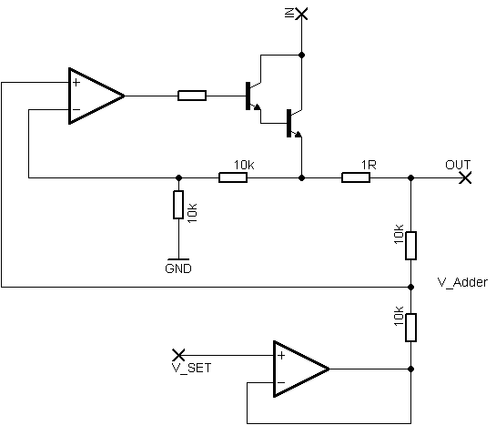
Rsense will cause Q2 to conduct when a threshold of approximately 0.65V is reached. Rbias will determine the extent of this limitation, although this aspect remains unclear. Particularly, if Rsense is positioned on the high side, simply activating Q2...
The sound system features a de-sensitized design with a maximum range that can be increased if desired. It includes two tone controls: one offering a lift of 10 dB and the other providing a subtle cut of 3 dB....
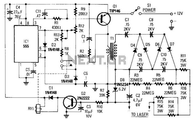
IC1 is a 555 timer operating at approximately 16 kHz. This integrated circuit drives Q1, a TIP146 transistor, which generates a 12-V square wave across the primary winding of transformer T1. This results in an output voltage ranging from...
The schematic of the power supply is illustrated below. It operates using standard household power of 120VAC at a frequency of 50/60Hz, with an adjustable output that can reach up to 25kV or higher. The power supply circuit is designed...
700W Amplifier. Adjusting the amplifier power to 700W appears straightforward, yet it is essential to consider the adjustment of the driving transistors and the frequency offset engagement. It is necessary to modify the current protection circuit that safeguards the...