
Digital displaying photoelectric counter circuit diagram

The circuit architecture consists of several key components that work together to process optical signals and convert them into a readable format. The optical input circuit, utilizing a photodiode (VD, 3DU12), is responsible for detecting incoming light signals. This photodiode generates a small current in response to incident light, which is then fed into the pulse forming circuit.
The pulse forming circuit is crucial for shaping the detected signals into a format suitable for further processing. It employs operational amplifiers IC1A and IC1B configured as a voltage comparator. This configuration allows for the detection of specific voltage levels, which corresponds to the presence or absence of optical signals. The output of the comparators is then sent to an optical coupler, which serves to isolate different sections of the circuit while allowing the signal to pass through.
Following this, a transistor switching circuit is implemented to control the flow of current based on the output from the optical coupler. This switching action is essential for driving the subsequent components of the circuit, ensuring that the detected signals can effectively trigger the counting and display circuit.
The counting and display circuit is designed to count the number of pulses generated by the pulse forming circuit and present this information visually. This component typically includes a microcontroller or a digital counter IC that processes the input signals and drives a display, such as an LED or LCD, to show the count. The integration of these components allows for real-time monitoring and visualization of the optical signals, making the circuit suitable for various applications in optical communication and signal processing.The circuit has optical input circuit (VD, 3DU12), pulse forming circuit (IC1A, IC1B form the voltage comparator; optical coupler; transistor switching circuit) and counting and display circuit.. 🔗 External reference
Related Circuits
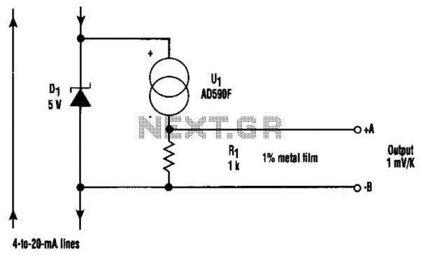
At the core of this circuit is the KTY10 temperature sensor from Siemens. This silicon sensor functions as a temperature-dependent resistor, integrated as one arm of a bridge circuit. A preset potentiometer (P1) is used to balance the bridge...
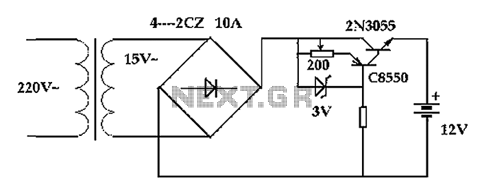
The circuit operates after a transformer, utilizing a bridge rectifier and conditioning for battery charging. The charging current transformer can be easily adjusted to provide approximately 12V at 100Ah battery charging. The required charging current is 10A, and a...
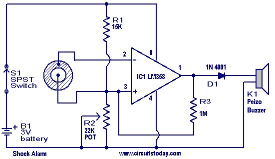
This is a simple shock-sensitive alarm circuit with numerous applications, ranging from home use to automobiles. The primary application of this circuit is as an anti-theft alarm for vehicles. A piezoelectric sensor is employed as the shock sensor and...
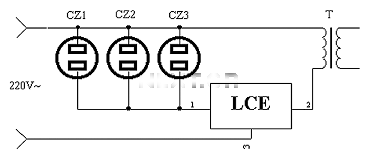
The application circuit operates as depicted below. It typically utilizes a shared TV antenna amplifier and an isolated power switch for the user. There are instances when the TV may not function, yet the antenna amplifier remains powered, leading...
In this circuit, an LM339 quad voltage comparator is used to generate a time delay and control a high current output at low voltage. Approximately 5 amps of current can be obtained using a couple of fresh alkaline D...
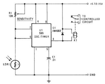
The following circuit illustrates a Photo Alarm Electronic Circuit. This circuit is based on the 555 Timer IC and incorporates features such as an LDR (light-dependent resistor). The Photo Alarm Electronic Circuit utilizes a 555 Timer IC configured in monostable...