
Electrical Circuit For Audi A4 Quattro

The electrical circuit for the Audi A4 Quattro 2004 model year encompasses critical components such as the transmission system and the anti-lock brakes (ABS) circuit. The transmission system is responsible for transferring power from the engine to the wheels, allowing the vehicle to operate efficiently. It is essential for maintaining optimal performance and fuel efficiency.
The anti-lock braking system is a safety feature designed to prevent wheel lock-up during braking, thereby enhancing vehicle control and stability. The ABS circuit typically includes components such as wheel speed sensors, an electronic control unit (ECU), and hydraulic valves. The wheel speed sensors monitor the rotational speed of each wheel and send this information to the ECU. If the ECU detects that a wheel is about to lock up, it activates the hydraulic valves to modulate brake pressure, allowing the wheel to continue turning and maintaining traction.
In this circuit, the integration of these components is crucial for ensuring that both the transmission and braking systems function seamlessly together. Proper wiring and connections are necessary to facilitate communication between the various sensors and the ECU, which processes the data and executes commands accordingly. Additionally, the circuit may include fuses and relays to protect the system from electrical faults and to ensure reliable operation under various conditions.
Overall, the electrical circuit for the Audi A4 Quattro 2004 model year is designed to enhance both performance and safety, incorporating advanced technology to meet the demands of modern driving.This circuit bellow shows an electrical circuit apply for Audi A4 Quattro 2004 model years. Component: Transmission, Anti-lock Brakes Circuit .. 🔗 External reference
Related Circuits
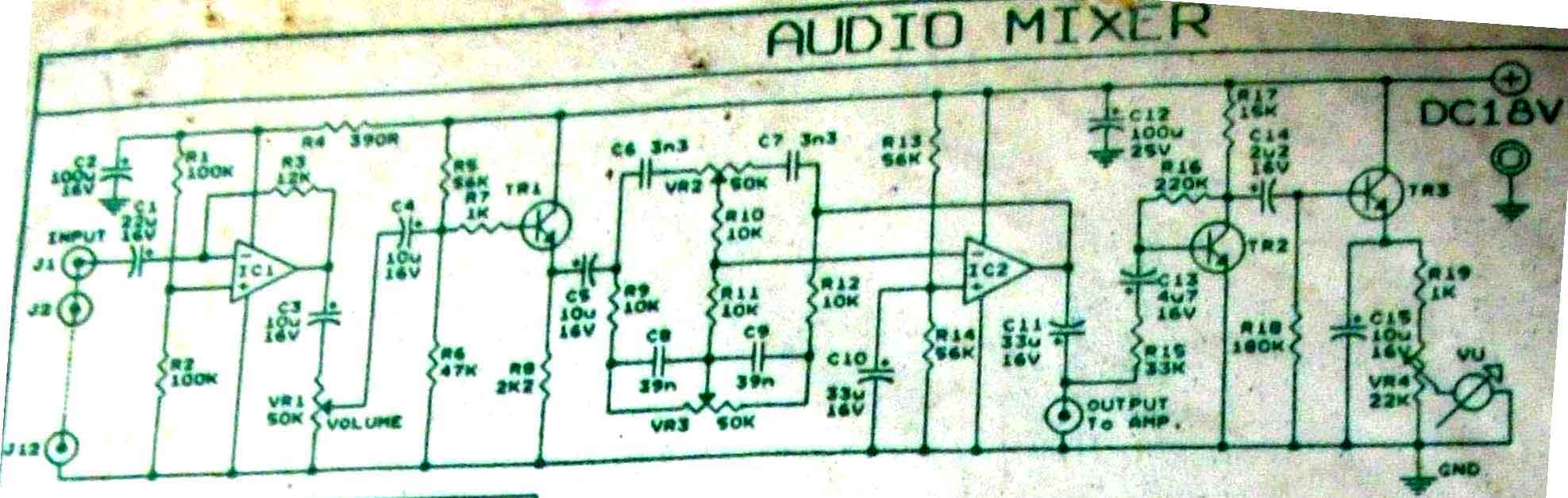
This is audio mixer circuit. The circuit is for one channel input, if you need, for example 5 channel mixer, then you need to build 5 similar circuits. The audio mixer circuit described is designed to handle a single channel...
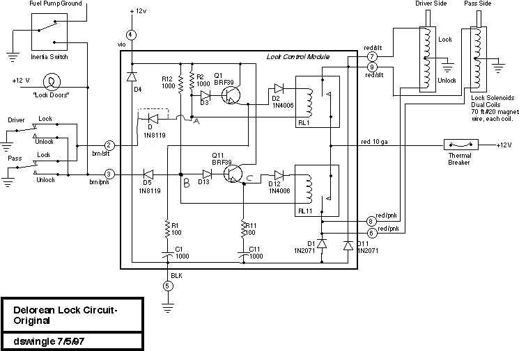
This document discusses the enhancement of a lock control module, providing instructions and photographs for upgrading the module to minimize its standby current consumption, thereby extending battery life. It is assumed that the user possesses a basic level of...
Listening to VHF FM offers significant advantages over MW/LW AM radio from earlier times, providing bright stereo sound free from interference, fading, and noise. However, FM radios lack the ability to predict thunderstorms as reliably as AM radios did...
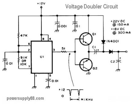
This circuit diagram represents a DC voltage doubler and DC converter. It is designed to convert a 12V DC power supply into outputs of 24V DC and 18V DC. Nearly any PNP or NPN power transistors can be utilized...
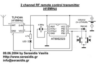
The following circuit illustrates a 3V power supply designed for an RF remote control circuit. This circuit is based on the AT90S2323 integrated circuit (IC). Features include a data rate of 2400 bps. The 3V power supply circuit for the...
The 2N3819 is an n-channel JFET specifically designed for RF and mixer applications, offering very low noise, minimal distortion, and excellent high-frequency gain. Creating a PCB can be accomplished in a few straightforward steps. Begin by using PCB design...