
VU Meter with Audio Mixer circuit

The audio mixer circuit described is designed to handle a single channel input. It is important to note that to create a multi-channel mixer, such as a five-channel mixer, five identical circuits must be constructed and integrated. Each circuit will typically consist of components that include operational amplifiers (op-amps), resistors, capacitors, and potentiometers.
The basic configuration of a single-channel audio mixer circuit may involve an op-amp configured as a non-inverting amplifier to boost the audio signal. The input audio signal is fed into the non-inverting terminal of the op-amp, while the inverting terminal is connected to a feedback resistor network, which sets the gain of the amplifier.
To allow for volume control, a potentiometer may be placed in series with the input signal. This allows the user to adjust the level of the input signal before it is amplified. Additionally, capacitors can be used for coupling, ensuring that only the AC audio signal passes through while blocking any DC offset that may be present.
For a multi-channel configuration, each channel would follow the same design principles, with individual volume controls and amplification stages. The outputs of each channel can then be mixed together at a summing point, which may also use an op-amp to combine the signals. The final output can be sent to a power amplifier or directly to speakers, depending on the application.
Overall, the construction of a multi-channel audio mixer requires careful attention to the layout and component values to ensure minimal noise and distortion, as well as proper matching of input and output impedances for optimal performance.This is audio mixer circuit. The circuit is for one channel input, if you need, for example 5 channel mixer, then you need to build 5 similar circuits. 🔗 External reference
Related Circuits
This article explains how to construct a general-purpose DTMF decoder using an affordable chip from MITEL. The circuit supports DTMF squelch based on a three-digit station ID (covering all 999 combinations). It can also decode four additional commands, which...
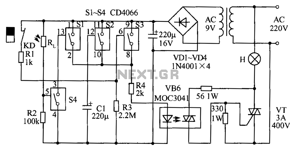
The circuit diagram illustrates a group of four analog electronic circuit switches (S1 to S4). Switches S1, S2, and S3 are utilized in a parallel delay circuit. When the power is activated, resistor R4 drives the triac VT, which...
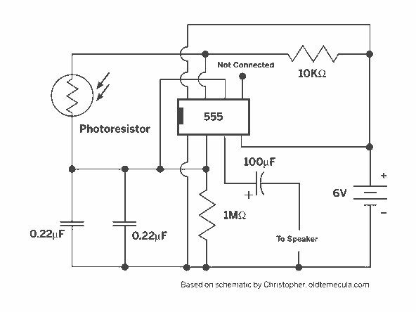
In the silicon-controlled trigger circuit, a cadmium sulfide cell is connected to a relaxation oscillator, which serves as a sensor to activate a blinking light in a darkroom. This setup causes a speaker to emit a warning sound of...
KA2213 is a single-chip record and playback integrated circuit produced by Samsung in South Korea. It is utilized in audio recording and playback devices. The internal circuit block diagram and pin functions of the KA2213 include a record and...
A light Theremin constructed using an oscilloscope panel, enhanced with a Joule Thief circuit. The design incorporates a 10 K variable resistor for pitch control and a 20 K variable resistor for volume control. The circuit is powered by...
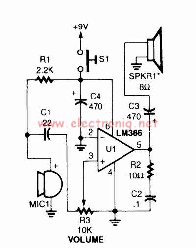
A voice amplifier can be designed using the LM386 power amplifier, which is intended for low voltage consumer applications. This simple circuit features variable gain and volume control. The gain is set internally to 20 to minimize the number...