
ElectricalCircuit For MR2 MKII Electric Aerial

The MR2 MKII electric aerial circuit is designed to facilitate the automatic operation of the aerial system. The circuit includes an Aerial Control Relay that acts as the primary switching component, allowing for the extension and retraction of the aerial based on user inputs or vehicle status. The relay is typically activated by a switch located on the dashboard or through a remote control system.
Key components of the circuit may include a power supply, which provides the necessary voltage for the operation of the aerial motor. The motor is connected to the relay, which serves to control the direction of the motor's rotation. When the relay is energized, it completes the circuit, allowing current to flow to the motor, thereby extending or retracting the aerial.
Additional features may include safety mechanisms such as limit switches that prevent the aerial from overextending or retracting beyond its designed range. These switches can interrupt the power supply to the motor when the aerial reaches its maximum or minimum position, protecting the motor from damage.
The circuit may also incorporate diodes for flyback protection, ensuring that any back EMF generated by the motor when it is turned off does not damage the relay or other sensitive components in the circuit.
Overall, the MR2 MKII electric aerial circuit is a well-designed system that enhances the functionality of the vehicle's aerial, providing convenience and reliability to the user.The following circuit shows about Electrical Circuit Diagram For MR2 MKII Electric Aerial. Features: controlled by an ‘Aerial Control Relay , consisting of .. 🔗 External reference
Related Circuits
This project is an extension of Metal Detector MkI, demonstrating the detection of metal objects. It is the second in a series of circuits that allows significant experimentation, particularly for those with a Cathode Ray Oscilloscope (CRO) and various...
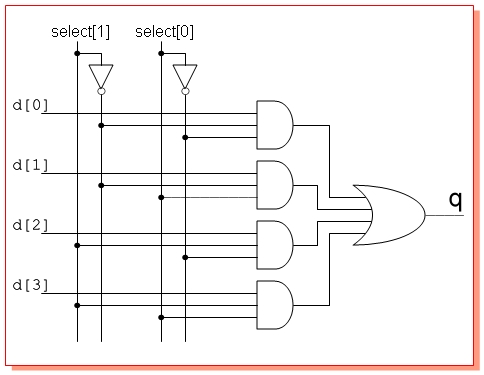
Design a circuit with four single-bit inputs X, Y, T, and Z, and a single-bit output E. A two-bit control code word S0S1 determines which of the four inputs is sent to the output (the selection code is not...
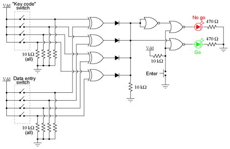
This experiment can be constructed using a single 8-position DIP switch, although utilizing two switch assemblies may facilitate a better understanding of the concept. One switch assembly is designated to hold the correct code for unlocking the lock, while...
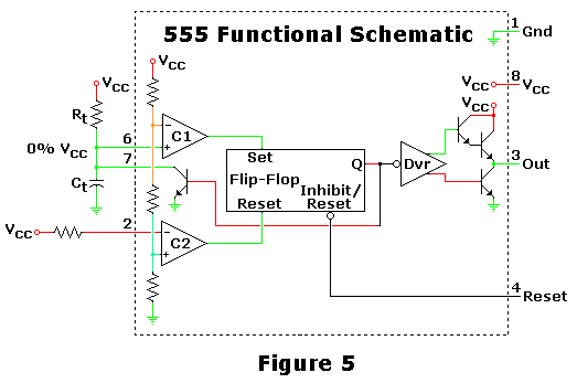
This is one of the most basic 555 circuits. This circuit is part of the chip's datasheet, complete with the math needed to design to specification, and is one of the reasons a 555 is referred to as a...
Magnetic pickups in musical instruments exhibit a relatively high output impedance, which can lead to a decrease in treble response when connected through long cable runs or to equipment with low input impedance. This preamplifier addresses these challenges by...
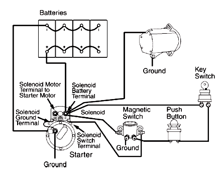
A circuit schematic for a basic heavy-duty electrical system that connects components such as the battery, starting motor, alternator, magnetic switch, ignition switch, and associated wiring. The heavy-duty electrical system circuit schematic is designed to provide reliable power management for...