
Electric Guitar/Violin Preamplifier

The described preamplifier circuit is designed to enhance the performance of magnetic pickups in musical instruments by effectively managing impedance mismatches and signal integrity. The use of JFET input transistors in the TL074 op-amp configuration ensures minimal signal distortion and high input impedance, which is crucial for preserving the tonal quality of the instrument. The AC coupling at the input stage prevents DC offset issues and allows for a clean signal to be amplified.
The adjustable gain feature, facilitated by the variable resistor VR1, enables users to tailor the amplification to suit different performance environments or personal preferences. The subsequent volume control via VR2 allows for additional flexibility in managing output levels. The parallel connection of the remaining op-amps (IC1b-IC1d) not only lowers the output impedance but also enhances the output drive capability, ensuring compatibility with a wide range of audio equipment.
The inclusion of series resistors for short-circuit protection is a critical design consideration, safeguarding the op-amps from potential damage due to unexpected load conditions. The output capacitors ensure that the DC level is appropriately managed, with the resistors at the output providing a safe operating condition for the circuit. The potential for adjusting the impedance of Output 2 via VR3 adds versatility, allowing for various connection scenarios without compromising signal quality.
In conclusion, this preamplifier circuit represents a well-engineered solution for addressing common challenges faced by magnetic pickups, ensuring that musicians can achieve optimal sound quality and performance reliability.Magnetic pick-ups in musical instruments have a relatively high output impedance. This can result in a reduction in treble response when connected via a long cable run or to equipment with a low input impedance. This preamplifier provides a high input impedance and a low impedance output, solving both issues. It has adjustable voltage gain and can run off a battery or DC plugpack. The input signal is AC-coupled to the non-inverting input of IC1a, part of a TL074 quad op amp. This has JFET input transistors and the input impedance is set by a 330k © bias resistor which also sets the DC level at this input to half supply (Vcc/2). This is generated by a voltage divider comprising two 10k © resistors and bypassed by a 47 µF capacitor to reject noise and hum.
IC1a is configured as a non-inverting amplifier with a gain of between 2 and 20, depending on the setting of VR1. IC1a`s output is fed to VR2 via a 22 µF capacitor, allowing the output volume to be set. The audio then passes to the non-inverting inputs of the remaining three op amps (IC1b-IC1d) which are connected in parallel to provide a low output impedance; it will drive a load impedance as low as 600 ©.
The 100 © resistors in series with the outputs provide short-circuit protection for the op amps and also prevent large currents from flowing between the outputs in case they have slightly different offset voltages. The buffered signal is then AC-coupled to two output connectors using 47 µF electrolytic capacitors. For Output 1, a 47k © resistor sets the output DC level to ground and a 220 © series resistor provides further short-circuit protection.
Output 2 is similar but includes another potentiometer (VR3) to allow its level to be set individually. Note that this means the impedance of Output 2 can be high (up to 2. 5k © depending on the position of VR3`s wiper). The total harmonic distortion of this circuit is typically less than 0. 01% with the gain set to six. If a TL064 is used instead of a TL074, the current drain will decrease but there will be more noise at the output.
Finally, the input impedance can be increased by increasing the value of the 330k © resistor to suit high-impedance pick-ups. 🔗 External reference
Related Circuits
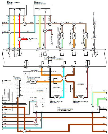
1995 Toyota Supra Electrical Circuit Diagram. Features: shown from the point where the power source is received from the battery as far as each component. The 1995 Toyota Supra electrical circuit diagram provides a comprehensive overview of the vehicle's electrical...
The circuit design utilizes a VHF amplifier configured to operate within the frequency range of 88 to 108 MHz, specifically for Band 2 radio applications. The VHF amplifier circuit is designed to enhance weak radio frequency signals in the specified...
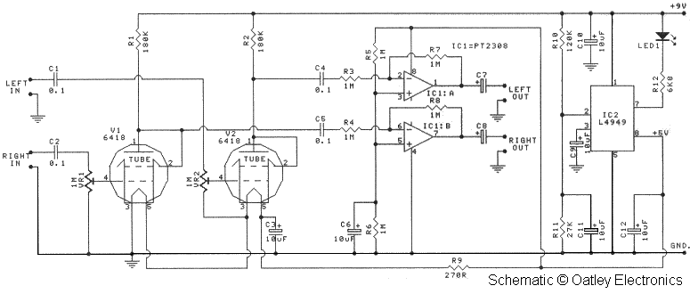
Oatley Electronics, located in New South Wales, Australia, offers several kits based on the Raytheon JAN 6418 sub-miniature valve (tube). The K272A Stereo Tube Preamplifier - Headphone Driver kit, priced at $27 AU, is one such kit. (Note: The...
In recent years, following CD's introduction, vinyl recordings are almost disappeared. Nevertheless, a phono preamplifier is still useful for listening to old vinyl discs from a well-preserved collection. This simple but efficient circuit devised for cheap moving-magnet cartridges can be...
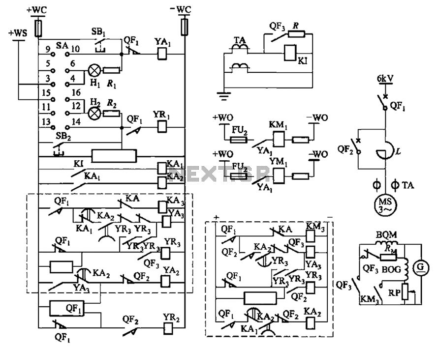
The circuit depicted in Figure 3-189 includes various components such as switch SA, closing button SBi, trip button SBz, de-excitation switch Yaa, and off trip coil YR3. The excitation switch contacts are represented by QF3, which serves as a...
A unit that is often very useful for isolating two stages in sound circuits. This circuit incorporates an amplification unit with a gain of X1. It employs only local negative feedback rather than total negative feedback, resulting in very...