
Electronic Ammeter and Voltmeter

The proposed circuit utilizes a Hall-effect current sensor for effective monitoring of the charging process in the sprite's electrical system. The Hall-effect sensor operates by detecting the magnetic field generated by the current flowing through a conductor. This method eliminates the need for shunt resistors, which can introduce significant power losses and heat dissipation issues.
In the schematic, the Hall-effect sensor is positioned within a toroidal core that is designed to concentrate the magnetic field. The core's dimensions are critical; a diameter of approximately one inch is recommended to prevent saturation and ensure minimal hysteresis. The wire used for the coil should be of sufficient gauge, such as no. 12, to accommodate several turns without compromising the sensor's performance.
The output from the Hall-effect sensor is fed into a microcontroller or an analog-to-digital converter (ADC) for further processing. This allows for real-time monitoring of the current flowing through the system, with the output voltage from the sensor being proportional to the current. The microcontroller can be programmed to display this information on a digital readout, allowing for easy interpretation of the charging status.
Additionally, the circuit may include a voltage regulator to stabilize the output voltage and ensure that the sprite's battery is charged efficiently. Proper thermal management should be considered in the design to prevent overheating, especially if high currents are expected. Heat sinks or active cooling solutions may be necessary to maintain optimal operating temperatures.
In summary, the proposed circuit design leverages a Hall-effect current sensor to provide accurate, efficient monitoring of the battery charging process, overcoming the limitations associated with traditional shunt-based measurements. This approach enhances the reliability of the sprite's electrical system while minimizing power loss and heat generation.I found that my sprite, burdened with an extra electrical load from an electric cooling fan, just barely kept the battery charged. My intended solution to this problem is an electronic voltage regulator; however, it seems obvious that, before changing the regulator, I need some way to monitor the charging.
Most meters today are digital. They work by converting an analog voltage to a digital number, displaying that number on a digital readout. Conventional analog meters are still in use, however, and probably will remain so. (To see why, just try to adjust something for a peak or null value with a digital meter!) Conventional meters are based on the principle that a coil of wire carrying a current experiences a torque when placed in a magnetic field. The torque rotates the coil, and a pointer connected to the coil indicates the current. Such meters respond fundamentally to current; we call them current-sensing devices. Voltmeters consist of an ammeter with a series resistance, so the voltage is measured, by Ohm`s law, as the current times the resistance.
Moving-coil ammeters can be remarkably sensitive. They are usually designed to operate at very low full-scale currents, because it is straightforward to extend their ranges to higher currents but not lower. Back when all test meters were analog, the "gold standard" was a movement that required only 50 microamperes for full-scale deflection.
To measure higher current, it is necessary to use a shunt, a resistor connected in parallel with the meter so that it bypasses most of the current. The shunt resistance is given by the relation, where Rs is the shunt resistance, Rm is the meter resistance, Im is the meter current for full-scale deflection, and Ifs is the desired full-scale value of the shunted meter.
This relation illustrates the problem in measuring high currents. If your meter has, say, a 1 milliamp movement (Im) and 100 ohms resistance (Rm), creating a 50-amp full-scale meter requires a shunt resistor of 0. 002 ohms, the resistance of a decent-sized chunk of copper. Such a shunt can be made, of course, but a fair amount of care in fabrication and calibration is necessary.
Here`s another problem. The meter I want to use is 1 mA full scale and has 700 ohms internal resistance. This meter would require a 0. 035-ohm shunt. That shunt, at full-scale current of 20 amps, would dissipate 14 watts and would drop the system voltage 0. 7V. That`s a lot of lost power and, especially, enough heat that we`d need to think carefully about cooling.
This just makes no sense; you shouldn`t have to spend 14 watts to get a simple current reading! My ammeter uses a current sensor based on a Hall-effect device. The device puts out a voltage that is proportional to a magnetic field to which it is exposed. The magnetic field is created by the current from the battery, which passes through a wire wrapped around a large toroidal core. The Hall-effect sensor is mounted in a gap in the core. There are a couple of important considerations in the design of the core. First, the core should be fairly large, about 1 inch in diameter, so that it is not saturated by the magnetic field, its hysteresis is minimal, and it can hold several turns of no.
12 wire. The permeability is not critical, but it should be reasonably large (100 or so), so the magnetic field is concentrated in the gap. The number of turns of wire on the core determines the range. The field strength should be such that the sensor output varies plus or minus about half a volt between current extremes; more, and it becomes significantly nonlinear.
Getting this right is just a matter of experimenting: mount the sensor in the gap and adjust the number of turns of wire on the core until the range is right. The gap shou 🔗 External reference
Related Circuits

A simple lab power supply electronic project can be designed using this circuit diagram, which is based on the LM2576 monolithic integrated regulator that provides all the active functions for a step-down (buck) switching regulator. As seen in the...
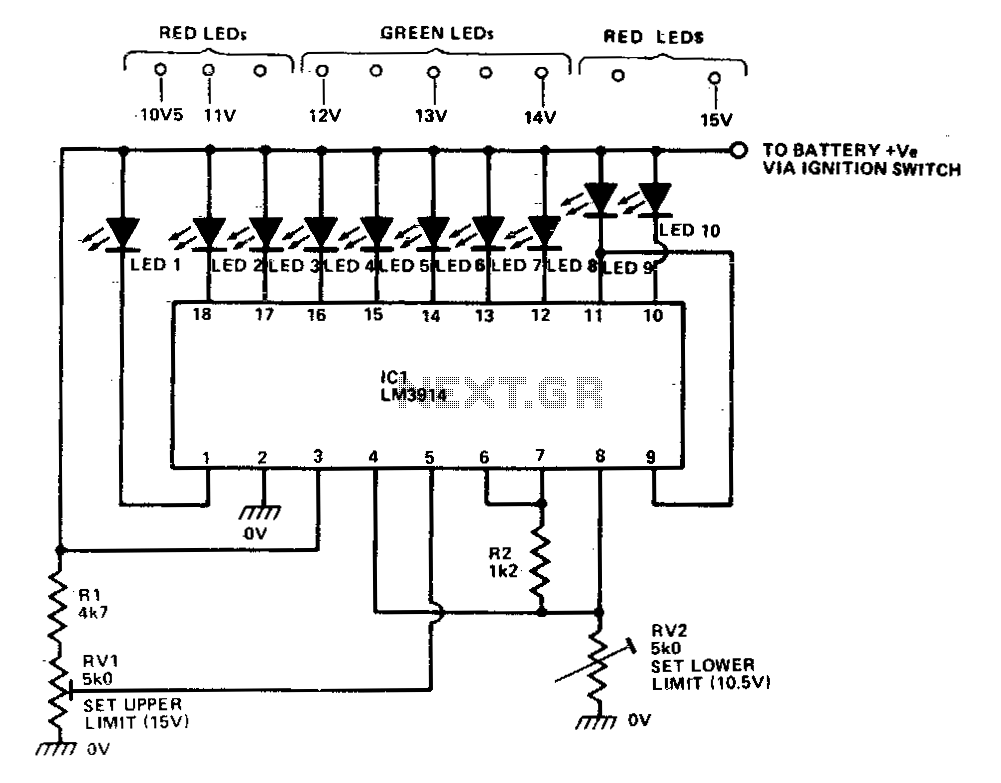
The LM39X4 functions as a LED-driving voltmeter, with its maximum and minimum readings determined by the resistor values R2 and RV2. When properly calibrated, the device operates within a 2-volt to 3-volt range but is designed to read supply...
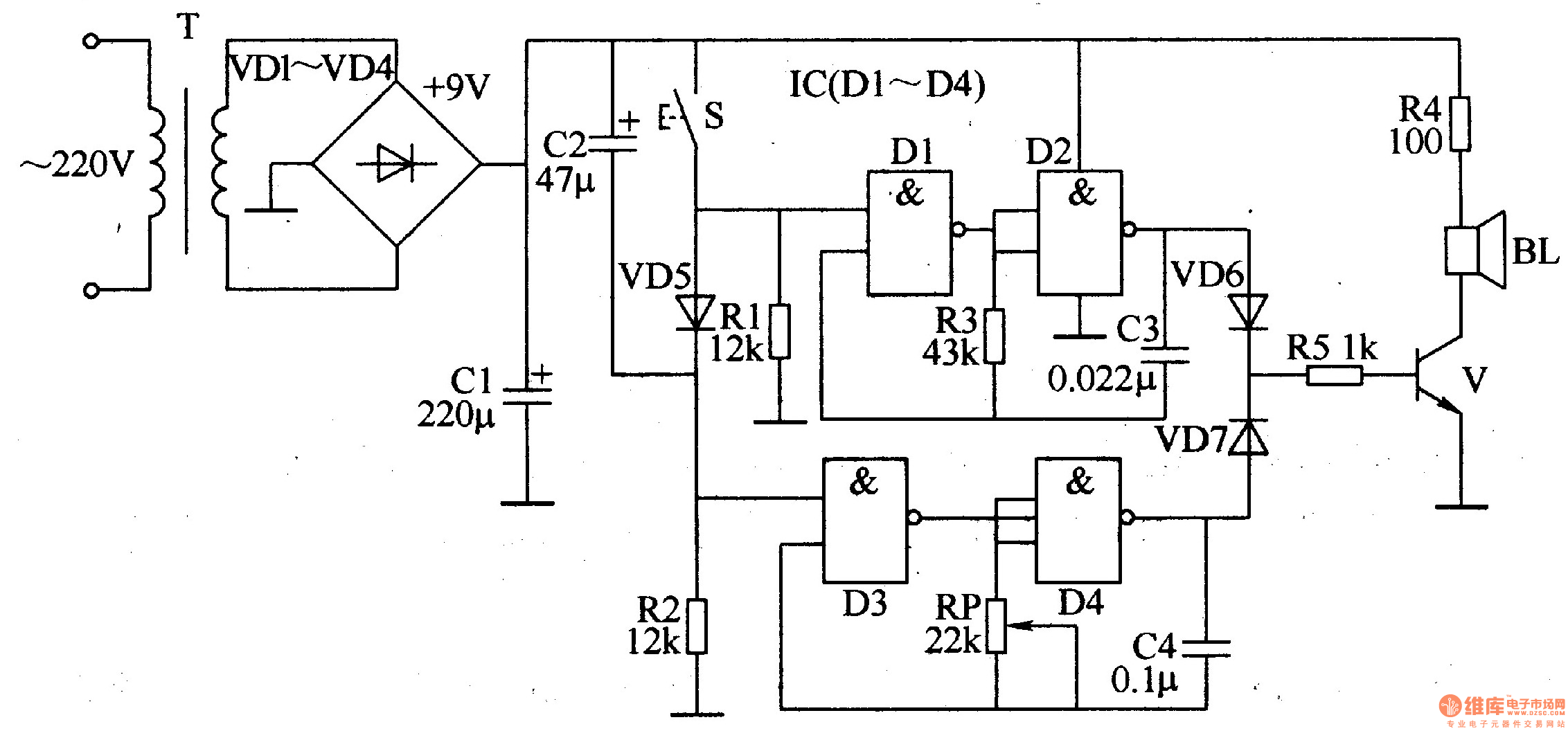
The ding-dong electronic doorbell circuit consists of a power supply circuit, a trigger control circuit, and an audio oscillator output circuit. The power supply circuit includes a power transformer (T), rectifier diodes (VD1-VD4), and a filter capacitor (C1). The...
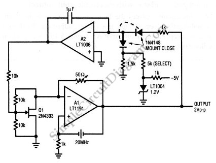
This is a quartz-stabilized oscillator circuit with electronic gain control. Replacing the common filament lamp for amplitude stabilization, this circuit uses... This circuit represents a quartz-stabilized oscillator featuring electronic gain control, which enhances the stability and precision of the output...
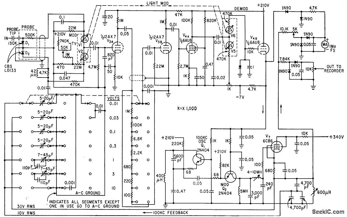
The circuit generates a low-frequency waveform with an amplitude that corresponds to an unknown RF voltage, utilizing a photochopper modulator (VI-V2) as an error detector. This arrangement provides seven voltage ranges from 10 mV RMS to 10 V RMS...

This liquid detector circuit diagram is designed using common electronic components. The liquid detector can activate an active buzzer to produce sound when a certain water level is reached. Since the water sensor and control circuit for the buzzer...