
Electronic balanced input microphone amplifier

The circuit design involves utilizing the RC4136 op-amp to create an electronically balanced transformer simulation. The RC4136 consists of four low-noise operational amplifiers in a single package, providing flexibility in circuit configuration and minimizing noise, which is crucial for achieving high CMRR values.
To implement this design, the following steps are typically taken:
1. **Circuit Configuration**: Each op-amp within the RC4136 can be configured for differential amplification. The input signals are fed into two of the op-amps, which will amplify the difference between them while rejecting common-mode signals.
2. **Resistor Selection**: Precision resistors are employed to set the gain of the amplifiers and to balance the resistor ratio. The resistor values must be carefully chosen to ensure that the gain of the inverting and non-inverting inputs are equal, which is essential for optimizing CMRR. The use of trimmer potentiometers allows for fine-tuning of the resistor values to achieve the desired balance.
3. **Feedback Network**: A feedback network is established around each op-amp to stabilize the gain and enhance linearity. The feedback resistors should match closely to maintain the integrity of the signal and prevent distortion.
4. **Power Supply Considerations**: The RC4136 requires a dual power supply (positive and negative voltages) to operate effectively. Proper decoupling capacitors should be placed near the power pins to filter out any noise from the power supply, ensuring that the op-amps function optimally.
5. **Testing and Calibration**: After constructing the circuit, it is essential to test the performance using a signal generator and an oscilloscope to measure the output. Adjustments should be made to the preset resistors until the desired CMRR is achieved, ensuring that the circuit performs as intended.
This electronically simulated transformer approach provides a compact, low-noise alternative to traditional transformers, with the added benefits of adjustable parameters for optimized performance in various applications.It is possible to simulate the balanced performance of a transformer electronically with a different amplifier. By adjusting the presets, the resistor ratio can be balanced so that the best CMRR is obtained. It is possible to get a better CMRR than from a transformer Use a RC4136 which is a quad low noise op amp.
Related Circuits
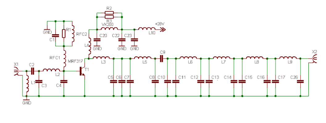
This power amplifier is equipped with a bipolar transistor, the famous MRF317. As in many FM amplifier applications, the power transistor is in a C class bias. All the impedance networks (input & output) have been determined by using...
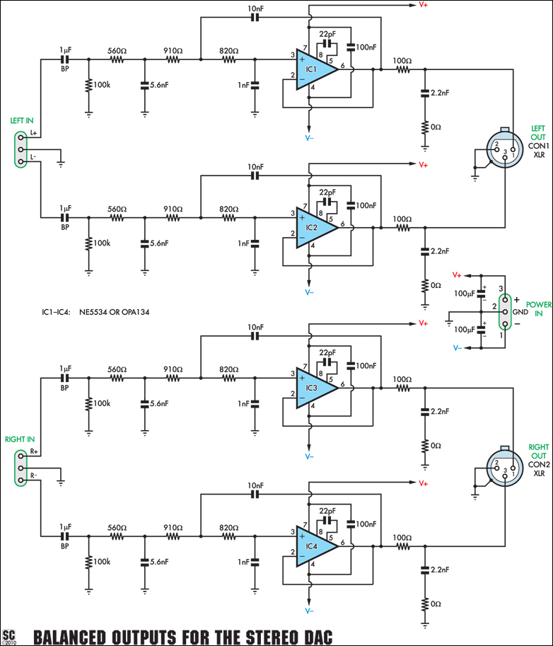
This add-on board is designed to provide a pair of balanced audio outputs for the High-Quality Stereo DAC (Digital to Analog Converter). Two 3-pin male XLR connectors are used for the new outputs, which can either replace or augment...
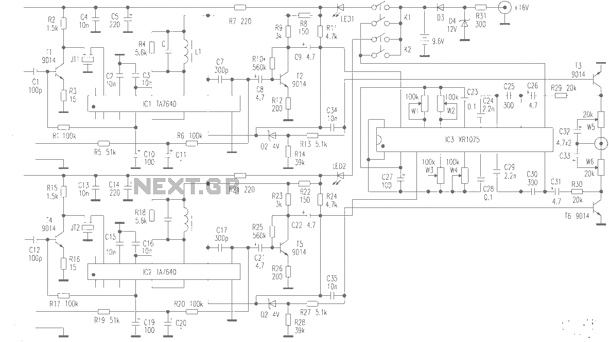
The production of high-quality wireless microphones is a common aspiration among enthusiasts, but achieving a high-performance receiver is challenging. This project explores the use of salvaged FM radio cassette players to enhance an XR1075 audio processor, leading to the...
This circuit is a class AB stereo audio power amplifier designed by Quasar for high-fidelity applications using a TDA2005 module. It is straightforward to construct and requires a minimal number of external components. The module includes output current protection...
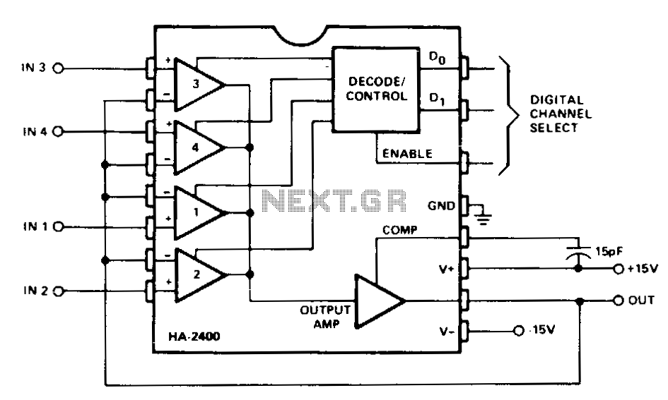
This circuit is utilized for analog signal selection or time division multiplexing. The feedback signal places the selected amplifier channel in a voltage follower (non-inverting unity gain) configuration, providing very high input impedance and low output impedance. The single...
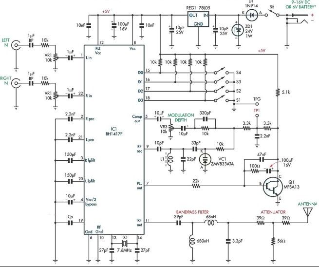
This stereo FM modulator circuit utilizes the BH1417F FM stereo transmitter integrated circuit (IC), which includes a stereo modulator for generating stereo composite signals and an FM transmitter for broadcasting an FM signal wirelessly. The stereo modulator produces a...