
Electronic Circuit Schematic DC Motor Driver using L293D Dual H-Bridge

According to the guidance provided in Figure 3, the motor will rotate clockwise when a logic high (1) is applied to input A and a logic low (0) is applied to input B. Conversely, the motor will rotate counterclockwise when input A receives a logic low (0) and input B is set to a logic high (1). To stop all motors, a logic high (1) must be applied to all input pins. It is crucial to avoid applying a logic low (0) to all inputs simultaneously, as this can lead to errors or damage to the L293D, potentially resulting in overheating or short circuits.
The L293D is a dual H-bridge motor driver capable of controlling the direction and speed of DC motors. Each H-bridge can control one motor, allowing for independent operation of two motors. The device features built-in diodes for back EMF protection, which is essential for safeguarding the circuit from voltage spikes generated by the motors during operation.
To implement the circuit, the L293D is connected to the power supply, motors, and a microcontroller or other control logic. The control signals from the microcontroller dictate the state of the inputs A and B for each motor. By using PWM (Pulse Width Modulation) on the enable pins of the L293D, speed control can also be achieved, allowing for variable motor speeds in addition to directional control.
Proper heat dissipation measures should be considered, as the L293D can generate heat during operation, especially under high load conditions. Heat sinks may be necessary to maintain optimal operating temperatures and prevent thermal shutdown. Overall, the L293D motor driver is a versatile component for robotics and automation applications, providing efficient control of DC motors in various configurations.According electronic schematic of DC driver motor using L293D in figure 2, we can use it to control two DC motor continuously. We can control DC motor one to rotate clock wise and DC motor two to rotate anti clock wise. We also can control all motor to rotate clock wise, anti click wise, or stop all. We can control it with give control in input of L293D. You can use guidance like in figure 3 bellow: From figure 3 above, we can make motor rotate clock wise when in input we give 1 logic in A and 0 logic in B. Also we can make motor rotate anti clock wise when input we give 0 logic in A and 1 logic in B. We can stop all motor with give in all input 1 logic. Attention you don`t give in all input with 0 logic, because it can make L293D error or damage like burn or shot circuit.
So careful when you set it. Thank you very much for your visiting in Robometricschool blog, We hope you will get more information about Robotic, Mechatronic, and Electronic. And don`t forget to give us your comment about this article. Let keep for building comment. 🔗 External reference
Related Circuits
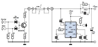
This circuit was designed to transmit commands over an LNB coaxial cable. An LNB (Low-Noise Block downconverter) is commonly used for satellite TV reception and is positioned at the focal point of a satellite dish. The circuit generates a...
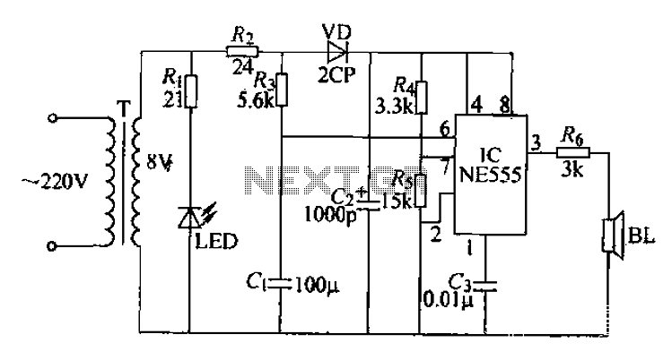
Electrical pulses are generated by the output of the first base circuit pin and sent through the R6 piezoelectric speaker, which converts the electrical pulses into ultrasonic waves. The circuit operates on a simple sweep principle, utilizing the transformer’s...
We are going to build a START-STOP drive (as commonly found in professional tools), that is a circuit with one switch to run the output (an LED in this case) and one switch to stop it. Nutchip feature two...
The EM4294 is an analog front end designed for high-security 13.56 MHz RFID reader systems. This reader integrates the cryptographic algorithm of the EM4035 transponder IC, which is associated with four secret keys. Each secret key has a length...
The fundamentals of crystals have not changed since this article appeared in a 1960 edition of Popular Electronics. The methods for growing, cutting, and packaging crystals have evolved significantly. Understanding their operation at the atomic level has also advanced...

The finish line circuit below detects the first of three cars to cross the line and illuminates a 25 watt 120 VAC lamp indicating the winning lane. Three photo transistors are used which can be embedded into the track...