
Racing Finish Line Lamps circuit

All ground symbols are connected to the negative side of the battery. All +6 points are connected to the positive side of the battery. Transistors and relays for #2 and #3 lights are not shown but are connected the same as shown for #1. A small LED may be substituted for the solid state relay (pins 3,4) for testing the circuit before the relays are installed. Pins 8,6 and 12 of the 74HC10 should read +6 volts after reset is pressed and light is shining on the photo transistors. Pins 1,9 of the top 74HC00 and pin 1 of the lower 74HC00 should read +6 volts with the reset button released. The same pins should read 0 volts with the button pressed. Pins 2,6,10,11 of upper 74HC00 and 2,6 of lower should read 0 volts after reset button is released and photo transistors are illuminated. Pins 3,4,8,12 of upper 74HC00 and pins 3,4 of lower should read +6 after reset button is released. Pins 9,10,12,13 of lower 74HC00 should be grounded.
Parts List:
Two - 74HC00 Quad, 2 input NAND gates - RSU 10880045 - $0.89 ea. One - 74HC10 Triple 3 input NAND gate - RSU 10880540 - .89 ea. Three - IR photo transistors - 276-145 - .99 ea. Three - MPS2222A NPN transistors - 276-2030 - .99 ea. Three - 1/4 watt 150 ohm resistors - 271-1312 - .49/5 Three - Solid state relays, 3 Amp/120VAC - 275-310 - 6.99 ea. Four - 1/4 watt 3.3K resistors - 271-1328 - .49/5 One - 470 uF/16 volt capacitor - 272-957 - .99 ea. One - 0.1uF capacitor - 272-135 - .69 ea. One - Momentary (normally open) push button - 275-1556 or 275-1571 One - 6 volt lantern battery or regulated power supply. Three - 25 to 60 watt 120VAC lamps and sockets.
The finish line circuit is designed to determine the first car to cross a designated finish line by employing an array of three infrared (IR) photo transistors. These sensors are strategically positioned along the track, with a focused incandescent light source illuminating the finish line area. When a car passes over a sensor, the IR light is obstructed, causing the corresponding photo transistor to switch state and signal the circuit.
The logic structure of the circuit utilizes a 3-input NAND gate configuration, where the photo transistors provide inputs. In the absence of a car, a logic low (0 volts) is present at the gate input. Upon detection of a car, the output transitions to a logic high (+6 volts), which is processed by a SET/RESET latch constructed from dual-input NAND gates (part of the 74HC00 IC). This latch activates a buffer transistor (MPS2222A) and subsequently controls a solid-state relay, which in turn energizes the lamp corresponding to the winning lane.
To ensure stability and prevent oscillation, unused NAND gates within the 74HC00 are grounded. A reset mechanism is integrated into the circuit, allowing for the manual clearing of the latch state via a momentary push button, which is essential for circuit initialization after power-up.
Component specifications include CMOS ICs, which require careful handling to mitigate static damage risks. The circuit can be tested using an LED in place of the solid-state relay for initial verification before final assembly. The circuit's performance can be monitored through designated pin voltage readings on the 74HC00 and 74HC10 ICs, ensuring proper functionality during operation. The assembly of this circuit necessitates standard electronic components, all of which are readily available from electronics suppliers.The finish line circuit below detects the first of three cars to cross the line and illuminates a 25 watt 120 VAC lamp indicating the winning lane. Three photo transistors are used which can be embedded into the track with a light shining down onto the finish line so that as the car crosses over the sensor, the light is blocked, activating the relay and lighting the lamp for the appropriate track.
The light source should be an incandescent type, florescent lights may not work due to low infra-red content. The circuit was tested using a 100 watt incandescent light fixture about 3 feet above the photo transistors.
The photo transistors are connected so that a logic low (0 volts) normally appears at the input to a NAND gate and as a car crosses the line blocking light to the transistor the logic level will move high (+6 volts). The resulting logic low level from the output of the gate (3 input NAND) is fed to a SET/RESET latch made from two dual input NAND gates (1/2 of a 74HC00) the (logic high) output of which controls the MPS2222A buffer transistor and solid state relay.
The inverted output of the latch (logic low) is connected back to the remaining two (3 input NAND gate) inputs locking them out. Two extra 74HC00 gates are not used and should have their inputs (pins 9,10,12,13) connected to ground to avoid possible oscillation.
The circuit is reset with a momentary push button connected to the reset side of each latch. The reset button may need to be pressed after power is first applied. Components for the circuit may be obtained from Radio Shack, however the RSU numbers may need to be special ordered or obtained from another source. The 74HC00 and 74HC10 are CMOS parts and should be handled carefully to avoid possible damage from static electricity.
You may want to use IC sockets so the wiring can be completed before the ICs are inserted into the sockets. You can briefly touch a grounded surface (computer chassis or other metal ground surface) just before handling CMOS circuits to reduce the possibility of damage from static electricity.
Notes: All ground symbols are connected to the negative side of the battery. All +6 points are connected to the positive side of the battery. Transistors and relays for #2 and #3 lights are not shown but are connected the same as shown for #1. A small LED may be substituted for the solid state relay (pins 3,4) for testing the circuit before the relays are installed.
Pins 8,6 and 12 of the 74HC10 should read +6 volts after reset is pressed and light is shining on the photo transistors. Pins 1,9 of the top 74HC00 and pin 1 of the lower 74HC00 should read +6 volts with the reset button released.
The same pins should read 0 volts with the button pressed. Pins 2,6,10,11 of upper 74HC00 and 2,6 of lower should read 0 volts after reset button is released and photo transistors are illuminated. Pins 3,4,8,12 of upper 74HC00 and pins 3,4 of lower should read +6 after reset button is released. Pins 9,10,12,13 of lower 74HC00 should be grounded Parts List: Two - 74HC00 Quad, 2 input NAND gates - RSU 10880045 - $0.89 ea.
One - 74HC10 Triple 3 input NAND gate - RSU 10880540 - .89 ea. Three - IR photo transistors - 276-145 - .99 ea. Three - MPS2222A NPN transistors - 276-2030 - .99 ea. Three - 1/4 watt 150 ohm resistors - 271-1312 - .49/5 Three - Solid state relays, 3 Amp/120VAC - 275-310 - 6.99 ea. Four - 1/4 watt 3.3K resistors - 271-1328 - .49/5 One - 470 uF/16 volt capacitor - 272-957 - .99 ea.
One - 0.1uF capacitor - 272-135 - .69 ea. One - Momentary (normally open) push button - 275-1556 or 275-1571 One - 6 volt lantern battery or regulated power supply. Three - 25 to 60 watt 120VAC lamps and sockets. 🔗 External reference
Related Circuits
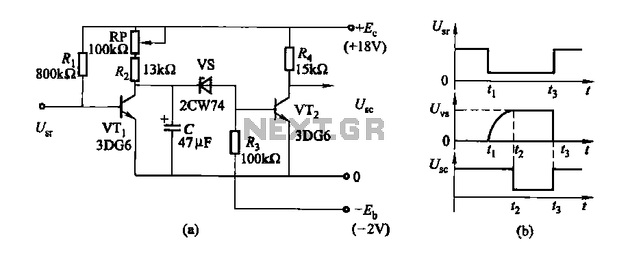
The delay time ranges from 0.5 to 3.5 seconds, which can be adjusted using the potentiometer RP to modify the delay duration. The circuit utilizes a timing mechanism that allows for the adjustment of delay intervals between 0.5 seconds and...

Standard LED flashers activate the LED in a rapid on-off sequence, which can become bothersome over time. The circuit presented here offers a more gradual illumination effect. This circuit utilizes a simple design to create a soft flashing LED effect,...
The telephone electronic ringer circuit is illustrated in the provided figure. It features an NPN transistor (either 9014 or 3DG12) as the primary component. The sound device, referred to as YD, functions as both a feedback device and is...

An innovative current detection method eliminates the power loss associated with the sense resistor in series with the motor. A 4-digit analog converter (DAC) facilitates digital control of the motor current path, simplifying the implementation of full, half, and...
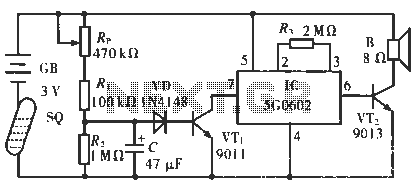
The circuit operates in such a way that when the patient is typically in an upright position, the SQ mercury switch is turned off, resulting in the alarm circuit being inactive. When the patient lies down, the SQ switch...
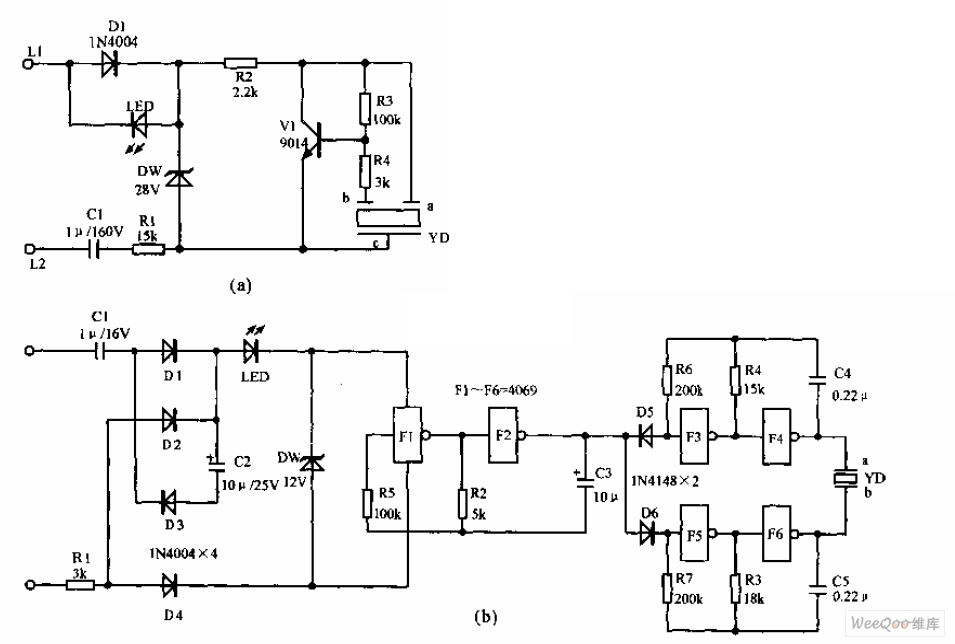
This document presents the circuit diagram of an IC-controlled emergency light with a charger, which functions as a 12V to 220V AC inverter circuit. The primary features of this circuit include automatic activation of the light during mains failure...