
Electronic combination lock

If, however, an unauthorized individual opens the door, closing switch S15 and providing a positive voltage to the emitter of Q1, the following sequence occurs: Transistor Q2 conducts, receiving the necessary biasing current through a current-divider network formed by resistors R3 and R4. As Q2 conducts, a voltage drop develops across the voltage dividers composed of resistors R5 and R6. With R5 valued at 10,000 ohms and R6 at 1,000 ohms, approximately one volt appears at the gate of SCR1, which is sufficient to trigger the SCR's gate.
The circuit described is a simple security system that utilizes transistors and resistors to create an alarm mechanism. The pressing of button S12 initiates the arming of the circuit, indicated by the illumination of LED1. The state of pin 1 of U1 being low is critical, as it allows for the activation of Q2 under specific conditions.
Transistor Q1 acts as a switch that controls the state of the circuit. When activated, it effectively enables the rest of the circuit to monitor the door status. The door switch S15 plays a pivotal role in determining whether the system remains in its armed state or triggers an alarm. In the armed state, Q2 remains off due to the lack of positive voltage at its emitter.
When the door is opened, switch S15 closes, allowing current to flow to the emitter of Q1. This action causes Q2 to turn on, facilitated by the current-divider network formed by R3 and R4, which biases Q2 to conduct. The subsequent voltage drop across R5 and R6 generates a sufficient voltage at the gate of SCR1, allowing it to trigger and potentially activate an alarm or alert system.
This circuit exemplifies a basic yet effective approach to intrusion detection, leveraging the characteristics of transistors and SCRs to create a reliable security mechanism. The design can be further enhanced with additional features such as a timer or a more complex alarm system, but the fundamental operation remains centered on the interaction between the components described.When button S12 (#) is pressed, a positive voltage fed through Rl appears at the base of transistor Ql, turning it on. When Ql is conducting, pin 1 of Ul is brought to ground 0ow) or the battery's negative terminal. With pin 1 low, two things occur: Pin 8 of Ul goes high ( + 9 volts dc), turning on LED 1—indicating that the circuit has been armed—and pin 13 goes from high to low.
Transistor Q2 requires a low signal or negative voltage on its base in order to conduct. It also needs a positive voltage on its emitter and a negative voltage on the collector. As long as the door switch (SI 5) remains open (with the door itself closed), Q2's emitter will not receive the necessary positive voltage. If, however, an unauthorized person opens the door, thus closing switch SI5 and placing a positive voltage on the emitter of Ql, the following sequence occurs: Transistor Q2 conducts, receiving the necessary biasing current through a current-divider network consisting of resistors R3 and R4. As Q2 conducts, a voltage drop is developed across the voltage dividers made up of resistors R5 and R6.
With R5 at 10,000 ohms and R6 at 1000 ohms, approximately one volt appears at the gate of SCR1. That's enough voltage to trigger the SCR's gate.
Related Circuits

A combination of a common-source grounded base amplifier formed by cascaded amplifiers. The source is grounded, and a common base amplifier is combined into a cascaded amplifier. The graph below shows the low noise characteristics of the FET common-base...
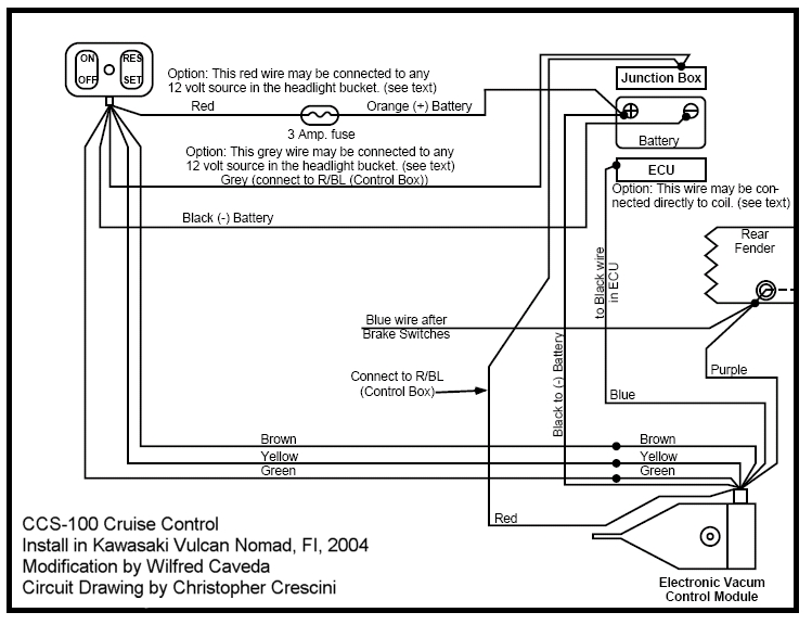
This project involves significant electrical wiring and requires modifications to the left side cover box, including drilling holes and making a slot. The gas tank must be removed, and careful reading of the instructions is essential. The Audiovox instruction...

A digital clock project utilizing the PIC16C54 microcontroller can be constructed using the provided circuit diagram. This electronic project features a time-of-day clock that includes four seven-segment LED displays and three input switches. Additionally, there is a reset switch...

A typical electronic volume control circuit is commonly used in stereo audio devices connected through a computer (CPU). The circuit adjusts the volume of stereo signals via input and output pins. Control signals are sent to the CPU (including...
Clocks have been discussed previously in relation to their interaction with flip-flops (FFs). It is important to note that a clock generates a timing signal used to control operations. This control mechanism is evident in both D and J-K...
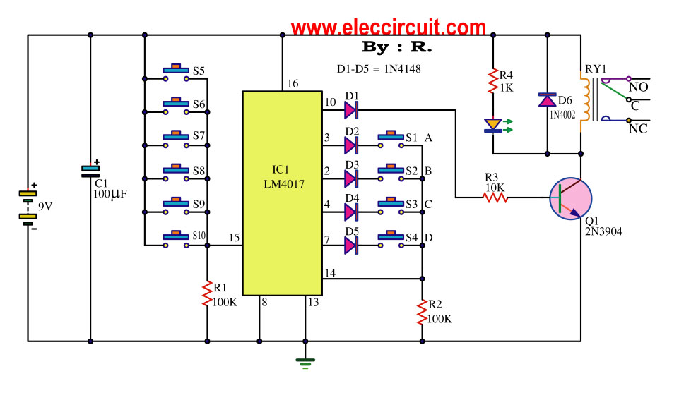
This key code switch circuit is an electronic circuit designed to replace conventional key switches, eliminating the need for physical key inserts. The key code switch circuit utilizes a microcontroller or a dedicated integrated circuit (IC) to interpret key codes entered...