
Electronic combination lock
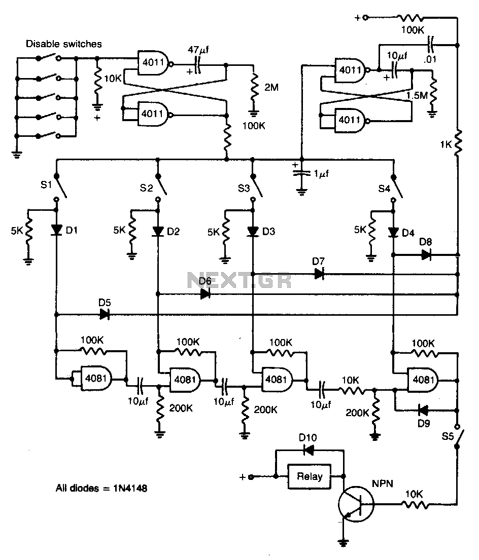
The described circuit utilizes a 10-button switch pad, allowing the user to input a specific sequence of switches (S1 to S5) to unlock a mechanism. The arrangement requires that these switches be activated in a precise order and within a rapid timeframe. The design can incorporate a microcontroller or a dedicated logic circuit to monitor the sequence of button presses.
When the correct sequence is entered, the microcontroller engages a relay or a similar locking mechanism, thereby granting access. Conversely, if an incorrect button is pressed at any point in the sequence, the circuit triggers an alarm. This alarm can be an audible sound, such as a buzzer, which alerts nearby individuals of the unauthorized attempt. Additionally, the circuit enters a lockout state for a duration of two minutes, during which no further inputs are accepted. This feature enhances security by preventing repeated attempts to guess the correct sequence.
To implement this system, a debouncing circuit may be necessary to ensure that each button press is registered accurately, avoiding false triggers from mechanical switch noise. The microcontroller can be programmed with a timer to manage the two-minute lockout period effectively, ensuring that the system resets and is ready for the next attempt after the timeout.
Overall, this switch-based locking mechanism provides a straightforward yet secure method of access control, suitable for various applications where user authentication is required.Switches SI through S5 must be operated in rapid sequence to operate the lock. They can be any numbers on a 10-button switch pad If an incorrect button is pushed, alarm sounds and the circuit is disabled for two minutes. 🔗 External reference
Related Circuits
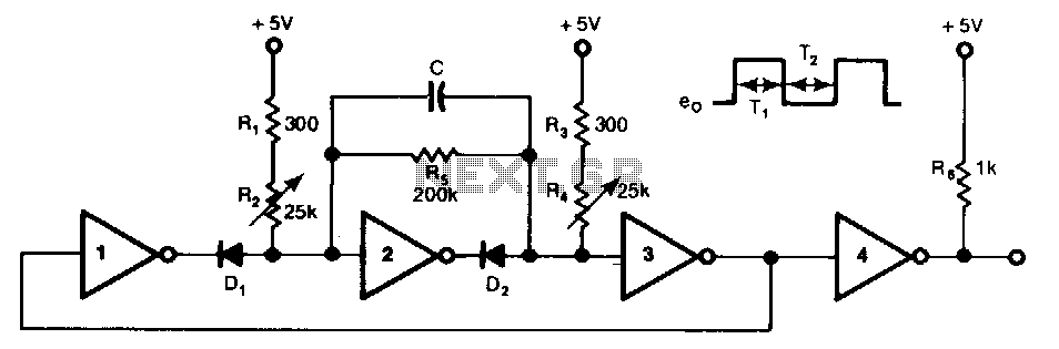
This free-running TTL square-wave oscillator features a variable frequency output spanning a 20:1 range or better. It utilizes four of the six inverters in an SN7404 chip along with additional components. The frequency of oscillation is dictated by the...
The circuit above makes use of the CMOS 4017 decade counter IC. Each depression of a switch steps the output through 0 - 9. By coupling the output via an AND gate to the next IC, a predefined code...
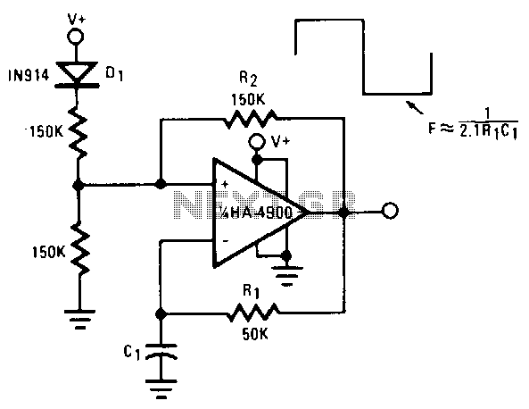
This self-starting fixed-frequency oscillator circuit provides excellent frequency stability. R1 and C1 form the frequency-determining network, while R2 delivers the regenerative feedback. Diode D1 improves stability by compensating for the difference between VaH and VsurrLY. In applications where a...
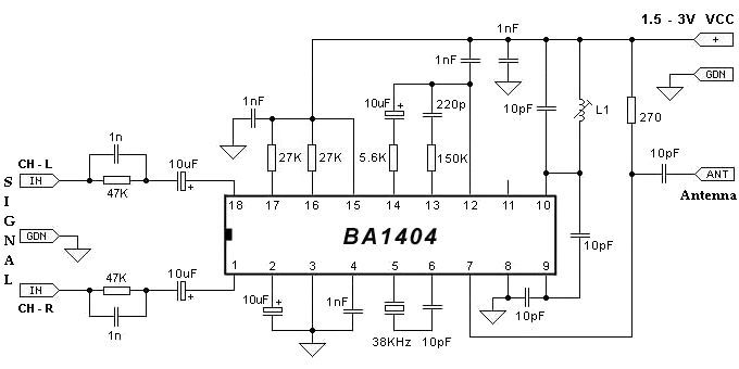
The BA1404 can be utilized to create a simple and effective FM stereo modulator electronic project. This BA1404 FM stereo modulator device operates within the FM broadcast band (75-108 MHz) and requires only a few common external components. The...
Multi-spark ignition is very useful especially in the case of startings at low temperature and at low rpm range. Basic idea, is to apply to spark plugs instead of only one spark, a spark-burst having big energy. In this...
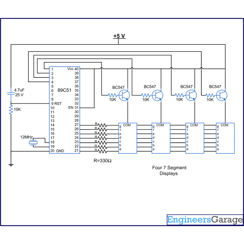
A digital clock displays time in a digital format. The circuit outlined here shows the time with double-digit minutes and two digits for seconds across four seven-segment displays. The segments of the displays are interconnected with the 8051 microcontroller...