
Electronic dice

The circuit design consists of six light-emitting diodes (LEDs) configured to visually represent the numbers one through six, as found on a standard die. The primary control mechanism is a push button input (PBI), which serves to toggle the display functionality. When the button is pressed, the display is blanked, effectively turning off the LEDs. Simultaneously, an oscillator circuit (IC1) comprising three integrated circuits (IC1 a, b, c) operates at a frequency of approximately 1 MHz. This oscillator provides a clock signal to a counter circuit (IC2), which is responsible for counting from zero to six. Upon reaching the count of seven, IC2 resets back to zero.
Once the PBI is released, the display is re-enabled, allowing the LEDs to illuminate based on the count maintained by IC2. The output from IC2 is processed by a decoding circuit (IC3), which interprets the binary count and activates the corresponding LEDs to represent the current count visually. This decoding system ensures that the correct pattern of illuminated LEDs corresponds to the value displayed on a traditional die.
The overall circuit operates in a straightforward manner, with the oscillator providing a consistent timing reference for counting, while the decoding circuit ensures accurate LED representation of the counted value. This arrangement not only serves as an effective visual display but also as a practical implementation of basic digital counting and decoding principles in electronic design.Six LEDs are arranged to produce a display the same as the dots on a dice. When PBI is depressed, the display is blanked and the oscillator (ICl a, b, c) clocks IC2 at about 1MHz. IC2 counts from zero and resets on seven When PBI is released, the display is enabled and a decoding system (IC3) produces the correct output on the LEDs.
Related Circuits
Utilize the program to customize your experience with the woven tules of roses on a single Adobe 3 Mac card. The system's reading portion remains idle while the controller operates, as illustrated in Figure 1. This setup includes the...
This circuit diagram illustrates a simple electronic combination lock utilizing the IC LS7220. The circuit is designed to activate a relay for controlling any device (turning it on and off) when a specific combination of four digits is entered....

The thermostat electric circuit operates as depicted in the figure. It has three settings: off, low power (Lo), and high power (Peru HL). When the DIP switch SA is set to the Lo position, 220V AC is directed through...
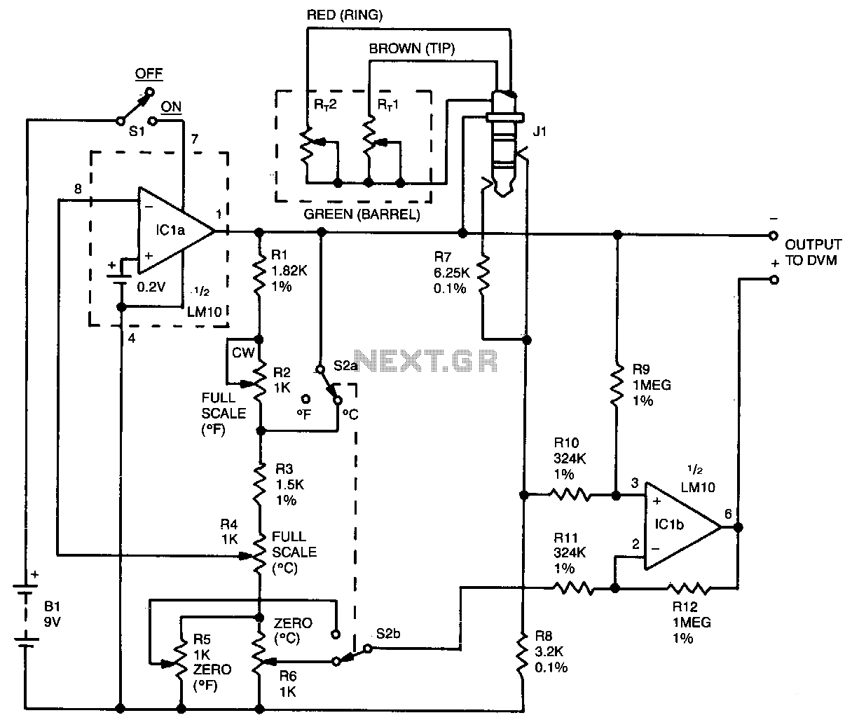
This oscillator circuit features a quartz crystal with a nominal resonant frequency of 262,144 Hz, which is cut in an orientation that provides a significant linear coefficient of frequency variation with temperature. In this configuration, the oscillation frequency is...
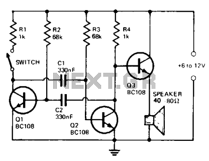
The circuit comprises a multivibrator (Q1 and Q2) and a low-power output stage (Q3). The speaker should have an impedance ranging from 40 to 80 ohms. To accommodate a low-impedance speaker, an output transformer should be connected from the...
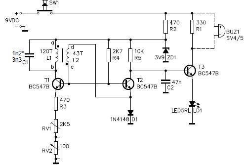
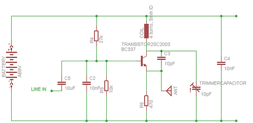
This metal detector circuit project is a simple design based on common electronic components. It utilizes transistors to provide a visual indication through an LED and an acoustic signal to alert users when metal is detected. To calibrate the...