
electronic door buzzer circuit schematic

The electronic door buzzer circuit is designed to provide an audible alert when someone presses the push-button switch S1. The LF351 operational amplifier serves as the core component, functioning as an oscillator to generate sound signals. The configuration utilizes positive feedback to achieve oscillation, which is essential for producing the sound output.
Upon pressing the S1 switch, a voltage is applied to capacitor C2, which charges and subsequently influences the non-inverting input of the LF351. The operational amplifier is configured in a feedback loop that causes it to oscillate, creating a square wave output. This oscillation is then sent to the connected speaker, which converts the electrical signals into audible sound waves.
The choice of speaker impedance is crucial for the performance of the circuit. A speaker with an impedance between 40 to 80 ohms is recommended to ensure optimal sound output without overloading the amplifier. The circuit is powered by a 9-volt DC power supply, which provides sufficient voltage for the operational amplifier to function effectively.
The simplicity of this circuit makes it an excellent project for beginners in electronics, allowing them to understand the principles of oscillation, amplification, and sound generation. Additional components such as resistors and capacitors can be added for fine-tuning the frequency and volume of the buzzer, enabling customization based on specific requirements.This electronic door buzzer circuit schematic has a very simple function and is very easy to build. This door buzzer circuit use a LF351 operational amplifier and other few common electronic components. When the S1 push-button is depressed an initial positive voltage is placed on the C2 and the non-inverting terminal of the LF351 operational ampl
ifier and the circuit will oscillate at a low frequency. The used speaker for this project must have a impedance between 40 -80 ohms. The door buzzer electronic circuit need to be powered using a 9 volts DC power supply. 🔗 External reference
Related Circuits
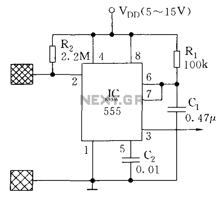
The proximity switch using the 555 timer functions as a monostable trigger circuit. The trigger pin (Pin 2) of the 555 timer is connected through a large resistor (R2) to the positive supply voltage (VDD) and is in a...
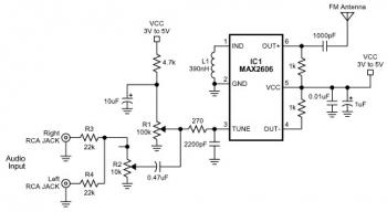
The FM transmitter circuit is built using a single MAX2606 chip. This simple FM transmitter connects a home entertainment system to a portable radio, allowing music to be played in one room and listened to in another, such as...

The microprocessor utilizes a linear regulator power circuit that is constructed using two MAX666 devices. The power supply for the CPU and A/D converter is connected to A2, while the RAM and real-time clock receive power from A1. The...
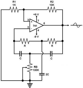
This circuit generates a sine wave using a single operational amplifier (741). The feedback loop of the op-amp includes a twin-T filter connected between its output and inverting input. Positive feedback for oscillation is provided by resistor R2. The...
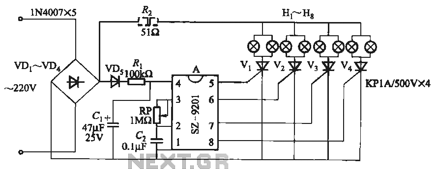
It utilizes the mains supply through a basic DC rectifier circuit. The circuit operates by converting alternating current (AC) from the mains supply into direct current (DC) using a rectifier. A typical implementation involves a bridge rectifier configuration, which consists...
The project involves the development of a miniature transmitter suitable for implantation in a rat's body, capable of transmitting 416-bit data samples at a rate of 400 samples per second. It is designed to have a detection range of...