
fm transmitter circuit with max2606

The FM transmitter circuit utilizing the MAX2606 chip is an efficient solution for wireless audio transmission within a limited range, making it particularly useful for home entertainment systems. The integration of a voltage-controlled oscillator (VCO) allows for precise frequency tuning, ensuring that the transmitter operates effectively within the FM band. The choice of a 390nH inductor for frequency setting is critical, as it directly influences the oscillator's performance, allowing for clear audio transmission without interference.
The circuit design incorporates a user-friendly interface for tuning and volume control. The potentiometer (R1) provides the flexibility to select different channels, which is essential for avoiding interference from other FM signals. The inclusion of resistors (R3 and R4) for audio signal summation is a standard practice in audio applications, ensuring that both left and right channels are mixed appropriately before transmission. The optional potentiometer (R2) serves a dual purpose: it not only adjusts the volume but also helps to prevent distortion by limiting the audio signal level fed into the transmitter.
For optimal performance, the transmitter should be paired with a suitable antenna. While a simple wire can suffice, the design emphasizes the importance of antenna placement and orientation to enhance reception quality. The operating voltage range of 3V to 5V ensures compatibility with various power sources, but stabilizing the supply voltage is recommended to maintain consistent operation.
The PCB design process outlined provides a straightforward approach for hobbyists and engineers to create their own FM transmitter. The use of readily available software tools and materials makes this project accessible, while the detailed steps for transferring the circuit design to a PCB ensure that even those with limited experience can successfully fabricate the transmitter. Overall, this FM transmitter circuit represents a practical and engaging project for those interested in exploring wireless audio technology.FM transmitter circuit which is build using single chip of MAX2606. A very simple FM transmitter connects your home-entertainment system to a portable radio that will be carried surrounding the house and into the back yard. As an example, it is possible to play music on the CD player in your private room, and listen to it on a portable radio by th
e back-yard barbeque. IC1 is a voltage-controlled oscillator with integrated varactor. Its nominal frequency of oscillation is set by inductor L1, and a 390nH value places that frequency at 100MHz. Potentiometer R1 then allows you to choose a channel by tuning above the FM band of 88MHz to 108MHz. Output power is about -21dBm into 50 (most nations accept emissions below 10dBm in the FM band). The home system`s left and right audio signals are summed by R3 and R4, and attenuated by the (optional) potentiometer R2.
R2`s wiper signal serves as a volume adjustment by modulating the RF frequency. Signals above 60mV introduce distortion, so the pot attenuates down from that level. In the absence of a common FM radio antenna, 75cm (30 inches) of wire will suffice as a transmitting antenna. For most effective reception, it need to be mounted parallel with the receiving antenna. The IC operates on a single power supply voltage inside the range 3V to 5V, but it is best to regulate the applied voltage to reduce frequency drift and noise.
Make a PCB in very easy steps. ! Create your PCB design using PCB designer software like Eagle, print out your design on photo paper or glossy paper with laserjet printer. Stick the printed design on the PCB (copper side) and then heat it using hot iron plate. The ink will stick on the PCB and it will be ready for etching process. Note: If you don`t have laserjet printer, then you can print the design on standard paper. Copy the printed design at Copy Service around your location (with glossy paper). 🔗 External reference
Related Circuits
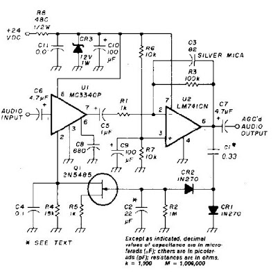
An audio signal applied to VI is passed through the operational amplifier 741, U2. After being amplified, the output signal V2 is sampled and applied to a negative voltage doubler/rectifier circuit composed of diodes CR1 and CR2, along with...
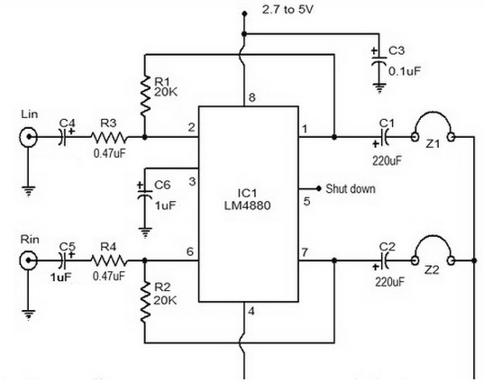
The LM4880 is a dual audio HiFi amplifier integrated circuit from National Semiconductor. This headphone amplifier circuit is specifically designed to produce high-quality audio output with a minimal number of components. The LM4880 integrated circuit is capable of delivering...
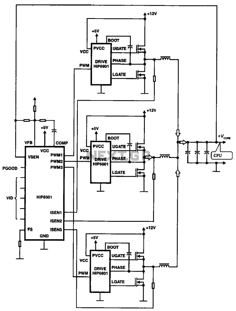
HIP6301 and HIP6601 are used in a 3-phase CPU power circuit. The HIP6301 and HIP6601 are integrated circuits designed for power management in CPU applications, particularly in multi-phase power supply systems. The HIP6301 is a high-performance synchronous buck controller,...
The tuner is programmable via I²C-Bus and provides a FBAS signal at its output. There is also the homepage of Georg Acher containing information about this tuner. A control circuit has been developed for this tuner using the AT89C2051...
The timing doorbell circuit utilizing the CW9300 is depicted in the provided diagram. This circuit features a timing function that, upon pressing the button, plays music for a specified duration. If the button is pressed again immediately after releasing...
This is a Mini MW (Medium Wave) Transmitter circuit. This circuit consists of a combination of transistors SA103 and SA101. These transistors are used as oscillators. The Mini MW Transmitter circuit is designed to operate in the medium wave band,...