
Electronic Door Release

This circuit utilizes a microcontroller or a simple logic circuit to interpret the key presses from the keypad. The microcontroller is programmed to recognize the specific sequence of key presses that constitute the valid code. The relay, which can be a standard electromagnetic relay or a solid-state relay, is responsible for controlling the power to the door-release mechanism.
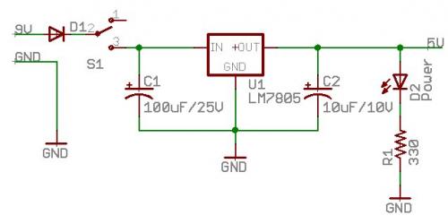
The power supply section of the circuit can include a voltage regulator if the input voltage exceeds the required levels for the microcontroller and other components. The use of decoupling capacitors near the power pins of the microcontroller ensures stable operation by filtering out noise.
To enhance user experience, an audible or visual indicator, such as a buzzer or LED, can be added to provide feedback on code entry success or failure. The design can also incorporate a timeout feature, where the system resets after a certain period of inactivity, further improving security and usability.
For assembly, the circuit board should be designed with careful attention to the layout, ensuring that the high-voltage relay is adequately isolated from sensitive low-voltage components. Proper trace widths and clearance should be maintained to prevent accidental short circuits and ensure reliable operation.
In summary, this circuit not only provides a secure method for controlling an electrical door-release mechanism but also offers flexibility for adaptation to various applications, making it a versatile choice for electronic projects.This circuit is designed to operate an electrical door-release mechanism - but it will have other applications. Enter the four-digit code of your choice - and the relay will energize for the period of time set by C4 & R4.
Use the relay contacts to power the release mechanism. The standby current is virtually zero - so battery power is a realistic option. The circuit is drawn with a 12-volt supply - but it will work at anything from 5 to 15-volts. All you have to do is choose a relay suitable for the supply voltage you want to use. Replace the SPCO/SPDT relay with a multi-pole relay - if it suits your application. Do not use the "on-board" relay to switch mains voltage. The board`s layout does not offer sufficient isolation between the relay contacts and the low-voltage components. If you want to switch mains voltage - mount a suitably rated relay somewhere safe - Away From The Board.
Choose the four keys you want to use as your code - and connect them to "A B C & D". Wire the common to R1 and all the remaining keys to "E". When you press your four keys - in the right order - the relay will energize. With the values of C4 & R4 as shown - and with R4 set to its maximum - the relay will de-energized about one minute after "D" is released. However - if you replace C4 with a 100nF capacitor - and replace R4 with a 4k7 fixed resistor - the relay will de-energize the moment "D" is released.
Any keys not wired to "A B C & D" are connected to the base of Q2. Whenever one of these "Wrong" keys is pressed - Q2 takes pin 1 low and the code entry fails. Similarly, if "C" or "D" is pressed out of sequence - Q4 or Q3 will take pin 1 low and the code entry will fail. If you make a mistake while entering the code - simply start again. The Keypad must be the kind with a common terminal and a separate connection for each key. On a 12-key pad, look for 13 terminals. The matrix type with 7 or 8 terminals will NOT do. A 12-key pad has eight "Wrong" keys connected to "E". If you need a more secure code - use a bigger keypad with more "Wrong" keys. The Support Material for this circuit includes a step-by-step guide to the construction of the circuit board, a parts list, a detailed circuit description and more.
🔗 External reference
Related Circuits

The input capacitor is used for low-frequency cut-off, with a standard value of 0.1 µF, resulting in a cut-off frequency of approximately 16 Hz. The input capacitor plays a crucial role in filtering unwanted low-frequency signals in electronic circuits. By...

The human infrared thermal release alarm can detect the infrared radiation emitted by the human body at any time of the day or night, triggering both sound and light alarms. This device is particularly suitable for electronic security applications....
This series of lectures is designed for individuals with a basic understanding of electronics, such as sophomores in Electrical and Computer Engineering, to explore the field of Embedded Electronics. It is assumed that the reader has a fundamental knowledge...
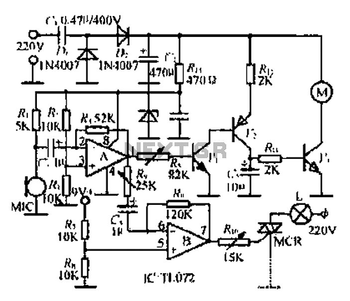
A microphone (MIC) is used to capture sound, which is then converted into a voltage signal. An operational amplifier (op-amp A) acts as a buffer; one output is directed to a motor drive circuit to control the motor's rotation...

The sensing element Q1 is a 2N3904 general-purpose NPN transistor, although any general-purpose NPN unit in a TO-92 style case will suffice. IC1, an LM334, provides Q1 with a constant current that remains stable regardless of temperature variations. An...
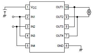
A simple forward-reverse motor control driver electronic circuit can be designed using the LB1948M, a two-channel low saturation voltage forward-reverse motor control driver IC. The LB1948M motor driver is suitable for use in 12V system products and can drive...