
LB1948M motor control driver electronic circuit design

The LB1948M motor driver IC is designed for efficient control of DC motors and stepping motors in various applications. It operates within a 12V power supply range, making it suitable for battery-operated devices and low-voltage systems. The low saturation voltage of 0.5V at a current output of 400mA ensures minimal power loss during operation, which is critical for enhancing the overall efficiency of the motor control system.
This motor driver supports multiple configurations, allowing for versatile applications. It can independently drive two DC motors, making it ideal for projects requiring simultaneous control of multiple motors. Alternatively, a single DC motor can be driven using a parallel connection, which can be beneficial in applications that require higher torque or where motor load sharing is necessary. Additionally, the IC is capable of driving a 2-phase bipolar stepping motor, providing flexibility for applications that require precise position control and variable speed operation.
The LB1948M features a zero-current draw in standby mode, which contributes to energy efficiency when the system is not actively driving motors. This feature is particularly advantageous in battery-powered applications, as it extends battery life by minimizing power consumption during idle periods. The braking function integrated into the driver allows for rapid deceleration of the motors, enhancing control and safety in applications where quick stops are required.
Moreover, the built-in thermal shutdown circuit protects the IC from overheating, ensuring reliable operation under varying load conditions. This feature is essential for maintaining the longevity and performance of the motor driver, especially in high-demand scenarios where motors may draw significant current.
Overall, the LB1948M motor driver IC is a robust solution for forward-reverse motor control in various electronic projects, providing essential features and reliable performance for both hobbyist and professional applications.A very simple forward reverse motor control driver electronic circuit project can be designed using the LB1948M 2 channel low saturation voltage forward reverse motor control driver IC. LB1948M motor driver is optimal for motor drive in 12V system products and can drive either two DC motors, one DC motor using parallel connection, or a 2-phase bip
olar stepping motor with 1-2 phase excitation mode drive. Some features of the LB1948M motor driver IC are : 12V power supply, low saturation voltage: VO(sat) = 0. 5V (typical) at IO = 400mA, zero current drawn in standby mode, braking function, built-in thermal shutdown circuit.
🔗 External reference
Related Circuits
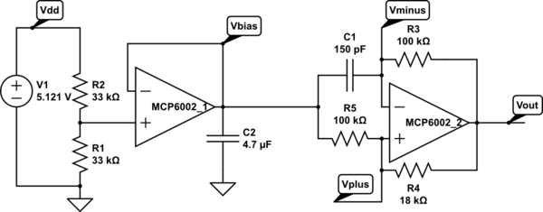
A touch sensor relaxation oscillator is utilized in the hysteresis lab. In this schematic, the variable capacitor is represented by a person's finger and a touch plate made from aluminum foil and packing tape. Code was developed for the...
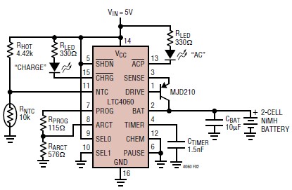
The LTC4060 integrated circuit can be utilized to create a straightforward smart NiMH battery charger electronic project. This charger circuit functions as a complete fast charging system for NiMH or NiCd batteries. It requires only a few external components...
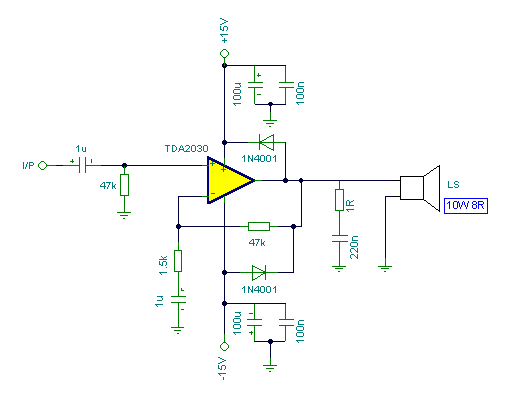
Connecting two TDA2030 through inexpensive power transistors allows for the creation of an amplifier capable of delivering higher power. This can be achieved by utilizing the component values specified in the schematic. To implement this circuit, two TDA2030 integrated circuits...
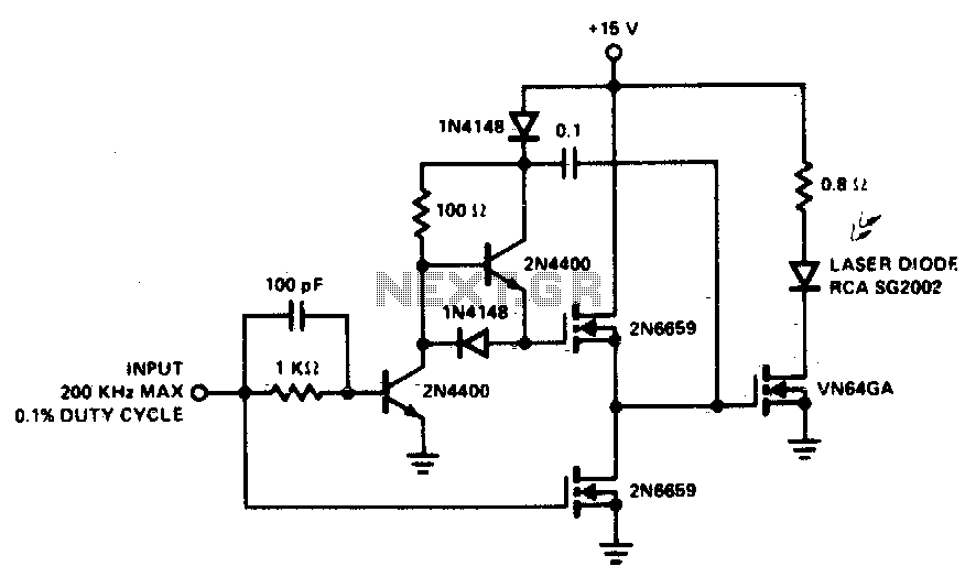
A faster driver can supply higher peak gate current to switch the VN64GA very quickly. The circuit uses a VMOS totem pole stage to drive the high power switch. The described circuit employs a high-speed driver to enhance the switching...
This circuit diagram represents a radio-controlled system, commonly utilized in toy car applications for children. The circuit comprises two main components: the transmitter and the receiver circuits. The transmitter circuit generates radio signals through an oscillator circuit built with...
This design is based on one published by Milan Lulic in the German magazine elektroModell. Mr. Lulic's design is for surface mount technology (SMT) construction, whereas mine uses standard off-the-shelf components, and is therefore better suited to construction by...