
Electronic Door Release

The electronic door release circuit serves as a secure access control system, allowing users to unlock a door by inputting a predetermined four-digit code. The core of the circuit typically includes a microcontroller, which processes the input code, and a relay module, which activates the door release mechanism upon successful code validation.
The circuit design begins with a keypad interface where users can enter the four-digit code. Each key press is detected by the microcontroller, which converts the input into a digital signal. The microcontroller is programmed with the correct code and logic to compare the entered code against the stored value.
Once the correct code is entered, the microcontroller sends a signal to the relay module. The relay, which acts as a switch, is energized, allowing current to flow to the door release mechanism. This mechanism can be an electric strike, magnetic lock, or any other compatible locking system. The relay remains activated for a predetermined duration, allowing sufficient time for the door to be opened.
Additional features may include an LED indicator to provide visual feedback on the status of the system, such as successful code entry or an error state. An audible buzzer can also be incorporated to signal incorrect attempts or to confirm successful unlocking.
For enhanced security, the circuit can be designed to limit the number of incorrect attempts before locking out further entries for a specific time period. This helps prevent unauthorized access through brute-force attempts.
The power supply for the circuit typically ranges from 12V to 24V, depending on the specifications of the relay and door release mechanism used. Proper attention must be given to the circuit layout to ensure reliable operation, including the use of appropriate resistors, capacitors, and protection diodes to safeguard against voltage spikes when the relay is activated.
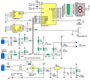
In summary, this electronic door release circuit combines user-friendly access control with robust security features, making it suitable for various applications beyond just door entry, such as securing cabinets or restricted areas.Electronic Door Release Circuit This circuit is designed to operate an electrical door-release mechanism - but it will have other applications. Enter the four-digit code of your choice - and the relay will energize for the perio.. 🔗 External reference
Related Circuits

The following circuit illustrates the iButton Electronic Lock Schematic diagram. This circuit is based on the Atmel AT89C2051 integrated circuit (IC). Features include an onboard power supply comprising a transformer (T1) and a voltage regulator (U4), a bridge rectifier...
Instructions for supervising landscaping projects recommended by satellite relay protection and automatic safety devices. This includes information on the general table for three remote programs related to petrochemical engineering construction, electrical transmission, and the intelligent implementation of community weak...
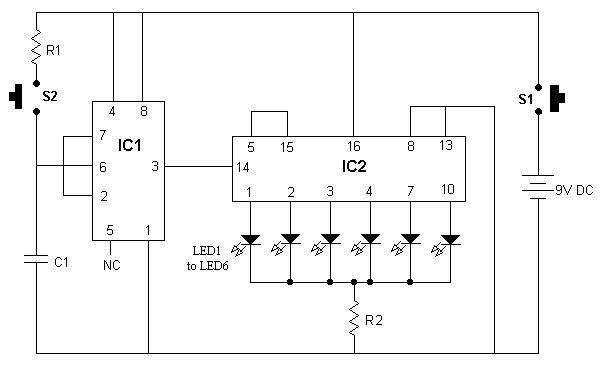
It is advisable to place this circuit in a box and label each LED with numbers 1 to 6. When switch S1 is pressed momentarily, one of the six LEDs will illuminate, and the number associated with the glowing...

This is an electronic coin toss circuit that utilizes a CD4049 integrated circuit (IC), which functions as a hex inverting buffer and TTL driver. The CD4049 contains six independent buffers that can be employed in various configurations, such as...

In some situations, a more complex approach is necessary, even when a simpler method is available. This scenario involves adding a second doorbell in parallel with an existing one. While this typically does not require additional electronic components, connecting...

A simple FM transmitter circuit can be designed using the MC2833 integrated circuit, which is intended for cordless telephones and FM communication equipment. It features a microphone amplifier, a voltage-controlled oscillator, and two auxiliary transistors. The final output frequency...