
iButton Electronic Lock Schematic Diagram

The iButton Electronic Lock circuit is designed to provide a secure locking mechanism controlled by a microcontroller, specifically the Atmel AT89C2051. This microcontroller serves as the core processing unit, executing the logic required to manage the locking system based on inputs from the iButton device.
The power supply section of the circuit is essential for ensuring stable operation. The transformer (T1) steps down the mains voltage to a lower AC voltage, which is then rectified by the bridge rectifier (VD9-VD12). This rectification process converts the AC voltage into a DC voltage suitable for powering the microcontroller and other components. The voltage regulator (U4) is employed to maintain a constant voltage level, which is critical for the reliable operation of the microcontroller and associated circuitry.
The circuit is designed to operate at a current of 20mA, which is sufficient for the microcontroller and peripheral devices without overloading the power supply components. The battery pack (BT1-BT10) consisting of AA batteries provides an alternative power source, ensuring that the lock remains operational even during power outages.
The ADM1232 IC plays a crucial role in the circuit by managing the reset pin of the microcontroller. This ensures that the microcontroller starts in a known state and can recover from any unforeseen issues, enhancing the overall reliability of the locking mechanism.
Other components in the circuit, such as capacitors, resistors, transistors, and diodes, are used for filtering, signal conditioning, and switching applications, which contribute to the overall functionality and efficiency of the electronic lock system. The inclusion of these components allows for improved noise immunity and ensures that the circuit operates smoothly under various conditions.
Overall, the iButton Electronic Lock circuit is a well-designed system that integrates various electronic components to achieve a secure and reliable locking mechanism, suitable for various applications requiring enhanced security measures.The following circuit shows about iButton Electronic Lock Schematic diagram. This circuit based on the Atmel AT89C2051 IC. Features: power supply on board (transformer T1, voltage regulator U4), bridge rectifier VD9-VD12, 20mA current, BT1-BT10 AA batteries, ADM1232 IC for mcu reset pin control, Component: IC, Capacitor, Resistor, Tra nsistor, Diode, Transformer. [high-voltage-lab. com] 🔗 External reference
Related Circuits
This is a convenient design for a transistor tester. The advantage of this circuit is that transistors can be tested without actually doing the circuit soldering. The tester uses two ICs: an NE 555 timer and a CMOS IC...
The metal detector circuit includes a fixed frequency oscillator, mixer, detector, detection oscillator, and power amplifier circuit. The fixed frequency oscillator circuit is composed of a ceramic filter (ZC), transistor (V1), resistors (R1 to R4), capacitor (C2), and other...
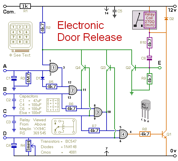
This circuit is designed to operate an electrical door-release mechanism, although it can be adapted for various applications. Users can enter a four-digit code of their choice, which will activate a relay for a duration determined by capacitor C4...
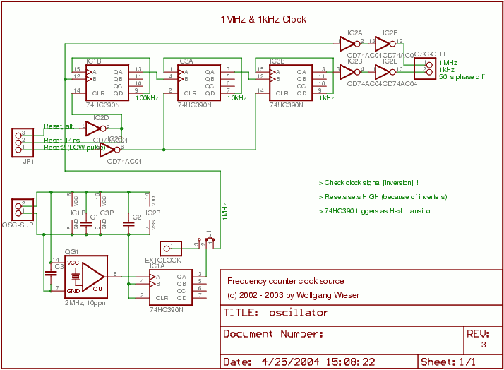
The oscillator generates a 1 MHz and a 1 kHz clock signal. The 1 MHz clock serves as the primary clock for the microcontroller and provides a time base for millisecond measurements. A 2 MHz signal is divided by...

Voltage variations and power cuts adversely affect various equipment such as TVs, VCRs, music systems, and refrigerators. This simple circuit will protect costly equipment from high and low voltages and voltage surges when power resumes. It also produces a...
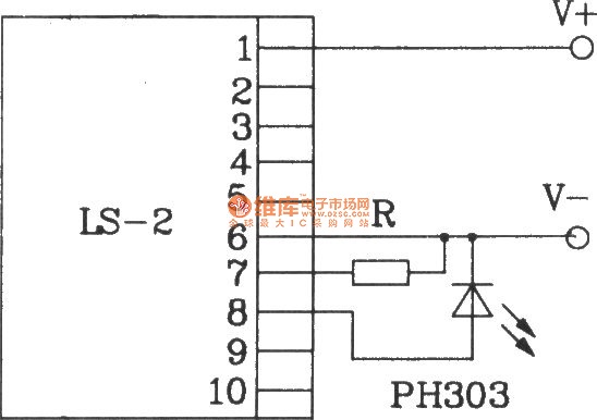
The LS-2 remote control switch infrared sensor module is similar to the LS-18 but functions as a reflector. The LS-2 pin diagram and internal block diagram provide insights into its electrical parameters. The operating voltage for the LS-2 remote...