
Electronic egg timer

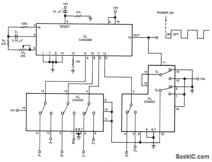
The astable multivibrator configuration is commonly utilized in various applications, including pulse generation, clock signals, and LED flashing circuits. In this design, the IC continuously oscillates between its high and low states without requiring any stable state, effectively creating a square wave output.
The external transistor plays a crucial role in controlling the frequency and duty cycle of the multivibrator. By adjusting the base current of the transistor, the timing of the output waveform can be modified. The configuration typically involves resistors and capacitors connected to the IC, which set the time periods for the high and low states of the output signal.
The toggle switch S1A/B allows the user to easily turn the circuit on or off, providing a straightforward interface for controlling the multivibrator's operation. When the switch is in the 'on' position, the circuit is activated, enabling the oscillation of the output signal. Conversely, when the switch is in the 'off' position, the circuit ceases to operate, stopping the oscillation.
Overall, this astable multivibrator circuit is an effective solution for generating periodic signals and can be adapted for various electronic applications by modifying the component values to achieve the desired frequency and output characteristics.The IC functions as an af multivibrator which is controlled by the external transistor S1A/B is the on-off toggle switch.
Related Circuits
The Hand Steadiness Tester is a game which tests the steadiness of your hand. The player has to take the ring from one end to another end without touching it to the wire. In this the player gets 4...
A wide range auto turn-off timer covering 1 minute to 20 hours in three ranges. The auto turn-off timer is designed to provide a versatile timing solution that can be set across a broad spectrum, from a minimum of 1...
This circuit provides a visual 9-second delay using a 7-segment digital readout LED. When the switch is closed, the CD4010 up/down counter is preset to 9, and the 555 timer is disabled with the output held high. When the...
The timer circuit provides independent control of the output's on and off intervals, which can range from 0.055 seconds to 30 minutes, with minimal impact from power-line transients. IC1 is a CMOS programmable timer chip that features 24 ripple-binary...
This is an electronic siren circuit diagram. The sound produced imitates the rise and fall of an American police siren. When first switched on, the 10µF capacitors are discharged, and both transistors are off. When the push-button switch is...
Phone In Use Indicator Electronics Project using 5 resistors, 2 NPN transistors, 4 diodes, and 2 light-emitting diodes. The Phone In Use Indicator is an electronic project designed to visually indicate when a telephone line is active. This circuit employs...