
Electronic Siren

The electronic siren circuit is designed to replicate the characteristic sound of an American police siren, which consists of a rising and falling frequency. The core components of the circuit include two transistors, capacitors, resistors, and a push-button switch.
Upon initial power-up, the 10µF capacitors are in a discharged state, resulting in both transistors being turned off. This state prevents any sound from being generated. The operation is initiated by pressing the push-button switch, which triggers the charging of the capacitors. As the capacitors charge, they create a voltage across the base of the first transistor, causing it to turn on.
Once the first transistor is activated, it allows current to flow through the circuit, which in turn begins to charge the second capacitor. The charging rate of the capacitor is controlled by the resistor values in the circuit, which dictate the timing of the rise and fall of the sound. The frequency of oscillation is determined by the RC time constant created by the resistors and capacitors.
As the first transistor conducts, the sound begins to rise. Once the voltage across the capacitor reaches a certain threshold, the second transistor is activated, allowing the sound to fall. This cycle of rise and fall continues as long as the push-button switch is held down. Releasing the switch results in the circuit returning to its initial state, where both transistors turn off and the capacitors discharge.
The circuit may also include additional components such as diodes for protection against reverse polarity and to ensure proper current flow. The design can be modified to adjust the frequency and volume of the siren sound by changing the values of the resistors and capacitors used in the circuit.
Overall, this electronic siren circuit serves as an effective demonstration of basic electronic principles, including transistor switching, RC timing circuits, and sound generation.This is Electronic Siren circuit diagram. The sound produced imitates the rise and fall of an American police siren. When first switched on the 10u capacitors is discharged and both transistors are off. When the push button switch is presse.. 🔗 External reference
Related Circuits
Voltage is applied to the chip via pins 14 and 7 so that when power is applied to the project, the high and low frequency oscillators will come into operation to produce a wailing sound from the piezo. The...
The circuit functions as a random number generator, producing numbers from 1 to 6. It features a line of LEDs, each corresponding to a number in the range of 1 to 6. When the push button S1 is pressed...
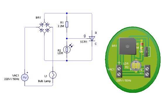
Adjust the value of R1 to achieve optimal performance of the LDR sensor. If, in practice, a resistance of 2.2 MΩ still activates the lamp, it is possible to increase the value of R1 to a larger resistance of...
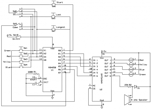
The MB Electronics Pocket Simon game features a straightforward circuit design, primarily due to the custom MB Electronics processor (MB4850) that handles most of the game's functions. The only other notable component is the SN75494N chip, which connects the...
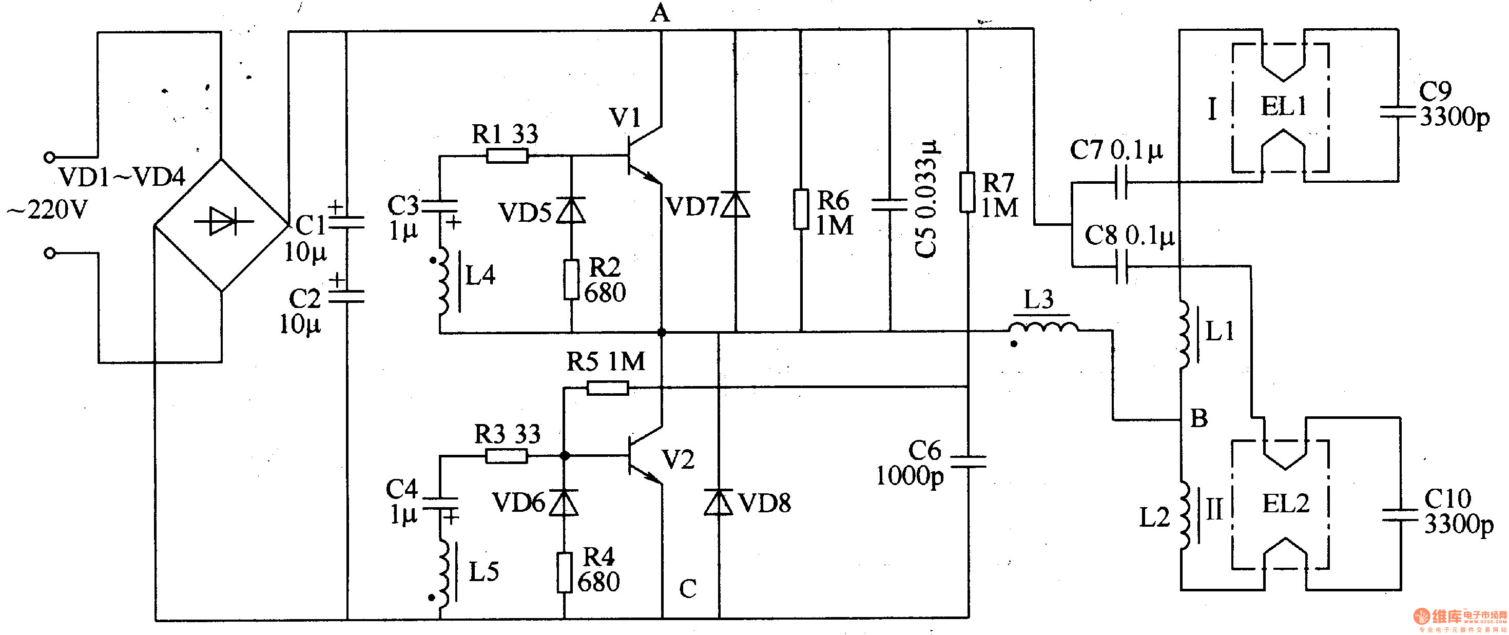
The electronic ballast circuit for fluorescent lamps comprises a rectifier filter circuit, a high-frequency oscillator circuit, and an output circuit, as illustrated in Figure 3-202. The rectifier filter circuit consists of rectifier diodes VD1-VD4 and filter capacitors C1 and...
The circuit is designed to operate with an audio power amplifier that uses 18V-0V-18V power rails. The specific voltage is not critical, but the feedback is referenced to an LED chain connected to a 12V rail, necessitating a separate...