
9 Second Digital Readout Countdown Timer

The described circuit utilizes a CD4010 IC, which is a dual 4-bit up/down binary counter. The counter is initialized to 9 when the switch is closed, allowing for a countdown sequence to begin. The 555 timer, configured in astable mode, is initially disabled to prevent any clock signal from being generated during this preset phase.
Once the switch is opened, the 555 timer is activated, generating a clock pulse approximately every second. This clock pulse is fed into the clock input of the CD4010 counter, decrementing the counter's value by 1 for each pulse. As the counter counts down from 9 to 0, the output of the counter is connected to a 7-segment display, which visually indicates the current count.
The design of this circuit ensures that the visual representation of the countdown is clear and straightforward. The 7-segment display is typically driven by the outputs of the CD4010, which are decoded to activate the appropriate segments of the display for each count.
This circuit can be effectively used in applications that require a timed visual indication, such as countdown timers or delay circuits in various electronic projects. The combination of the CD4010 and the 555 timer provides a reliable and simple method for achieving a precise timing function with visual feedback.This circuit provides a visual 9 second delay using a 7 segment digital readout LED. When the switch is closed, the CD4010 up/down counter is preset to 9 and the 555 timer is disabled with the output held high. When the switch is opened, the timer produces an approximate 1 second clock signal, decrementing the counter until the 0 count is reached.
When the.. 🔗 External reference
Related Circuits
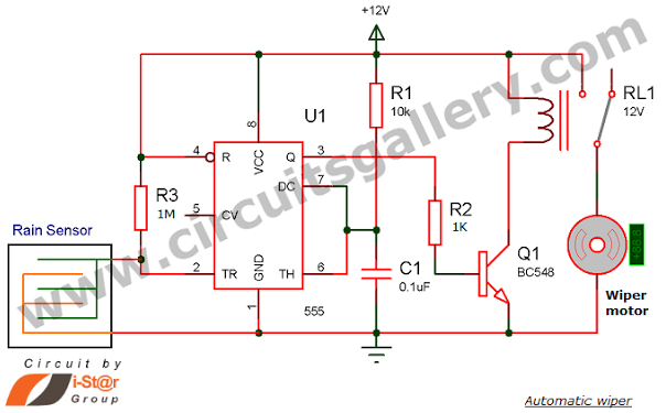
Have you seen Audi, Lexus, or Ford rain-sensing wipers and wondered how they operate in these vehicles? They are controlled by sensors located at the center of the windscreen, which detect raindrops and activate the wiper motor. The functioning...
This circuit is designed to digitally adjust the volume of an analog audio signal. It employs a single AVR microcontroller to generate a pulse width modulated (PWM) signal for control. The innovation of the circuit lies in the utilization...
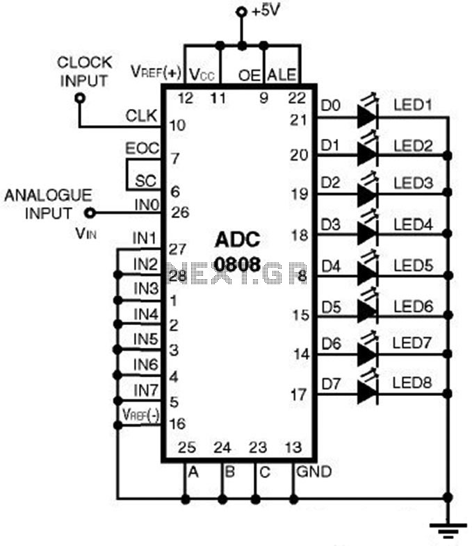
This is a straightforward analog-to-digital converter circuit utilizing an 8-bit analog-to-digital converter (ADC0808). Typically, an analog-to-digital converter (A/D Converter / ADC) necessitates interfacing with a microprocessor to convert analog signals. The ADC0808 is a widely used 8-bit A/D converter that...
This is an enhanced version of the Darkroom Timer initially developed by Stan Ockers in 1999. Additional features have been incorporated, and the PIC code has been accordingly modified. The complete schematic, PCB layout, and silkscreen are provided in...
Many friends take an interest in the circuit involving the highly popular IC 555, which is an integrated circuit. This circuit sets the time in a basic manner. The IC 555 timer is a versatile and widely utilized component in...

The following circuit illustrates a Bedside Lamp Timer Circuit Diagram. This circuit is based on the CD4060 integrated circuit. Features: An LED illuminates for approximately 25 seconds. The Bedside Lamp Timer Circuit utilizes the CD4060 IC, which is a versatile...