
Electronic flash trigger

Resistor R4 limits the discharge current from C2 at the conclusion of the timing cycle, thereby protecting the IC. An LED, along with its protective resistor R5, functions as an indicator to show that the unit has been triggered, which simplifies the setup process and minimizes the frequency with which the strobe must be activated. Consequently, the strobe does not need to be fired until a photograph is ready to be taken.
The circuit operates by utilizing a negative pulse from an external source, which is coupled to the IC through capacitor C1. This capacitor not only serves to block any DC component but also ensures that only the AC signal (the negative pulse) reaches the triggering input of the IC. The voltage divider formed by R1, R2, and RV1 establishes a reference voltage that is crucial for the proper operation of the triggering mechanism.
Once the IC is triggered, the output at pin 3 goes high, activating the timing components, which include RV2, R3, and C2. The timing duration can be adjusted using RV2, offering flexibility in controlling how long the output remains high. Upon reaching the end of the timing period, the output drops low, causing capacitor C3 to discharge through the SCR's gate-cathode junction, which then turns on the SCR and initiates the flash.
Resistor R4 plays a vital role in safeguarding the IC by limiting the discharge current from capacitor C2, thus preventing potential damage during the timing cycle. The LED indicator, in conjunction with resistor R5, provides visual feedback to the user, confirming that the flash has been triggered. This feature is particularly beneficial in scenarios where precise timing is essential, as it allows the user to verify the system's readiness without unnecessary activations of the strobe. Overall, this circuit design effectively combines sensitivity control, timing mechanisms, and user feedback to create a reliable flash triggering system suitable for photographic applications.A negative pulse at the input is fed via capacitor Cl to the input pin (2) of the IC, Pin 2 is held slightly above its triggering voltage of 1/3 Vcc by the voltage divider comprising Rl, R2 and RV1, The negative pulse triggers the IC and the output (pin 3) goes high for a time period controlled by RV2, R3 and C2. When the output goes low again at the end of the time interval, capacitor C3 charges through the gate cathode circuit of the SCR switching it on and firing the flash.
Capacitor Cl isolates the input from the voltage divider so that the unit isn't sensitive to the dc level at the input. RV1 acts as a sensitivity control by allowing the voltage to be adjusted to a suitable level so that the input signal will trigger the IC.
Resistor R4 limits the discharge current from C2 at the end of the timing cycle protecting the IC. The LED and its protective resistor R5 act as an indicator to show that the unit has triggered, simplifying the setting up process and minimizing the number of times the strobe has to be fired. This means that the strobe needn't be fired until a photo is to be taken.
Related Circuits
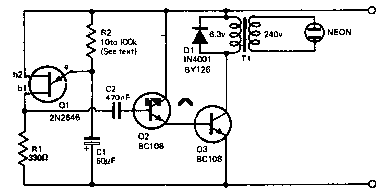
The voltage required to ignite the neon tube is generated by utilizing a standard filament transformer (240-6 V) in reverse. The battery drain is minimal, approximately 1 to 2 milliamps for a nine-volt battery. The pulses from Q1, a...

A simple electronic combination lock using the IC LS7220. This circuit employs a relay to control any device when a combination of four digits is entered. Keypads serve as the input method for entering the digits, and the correct...
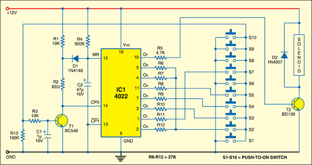
This 7-digit combination lock can be easily hard-wired for any combination that you choose. The circuit utilizes a 4-bit, divide-by-8 Johnson counter (IC1), ten push button switches, and an NPN transistor (T1). Upon power-on, capacitor C2 connected to pin...
The circuit illustrates how the combination of a blue LED and a white LED can be utilized to create a realistic imitation of a camera flashlight. The circuit design employs a blue LED and a white LED in conjunction to...

When we step on the car's brake, then together with the classic rear STOP, the third STOP which is situated in the middle of the back half of the car also switches ON. This is the classic function, found...
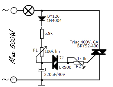
This flashing light circuit utilizes triacs to produce an intermittent light with a variable frequency. Additional components include a diode (D1) and a semi-adjustable potentiometer (R2). The trigger capacitor (C1) is increased from 0.1 µF to 220 µF to...