
Electronic Key Circuit

The circuit utilizes the CD4017 decade counter, which is designed to count up to ten and can be configured to detect specific sequences. Four push-button switches are connected to the input of the CD4017, each corresponding to a unique output pin. The logic gates are employed to ensure that the sequence of button presses is validated before activating the relay.
When the first button is pressed, the CD4017 advances to the first output. If the second button is pressed next, the counter will move to the second output, and this continues until all four buttons are pressed in the correct order. If the sequence is completed successfully, a logic high signal is sent to the relay control circuit, energizing the relay and allowing it to switch on the connected load.
In addition to the main components, the circuit may include debounce circuitry to prevent false triggering from mechanical vibrations when the buttons are pressed. This can be achieved using additional logic gates or capacitors in conjunction with resistors. The relay itself can be of various types, depending on the load requirements, and should be selected based on the voltage and current specifications of the intended application.
Finally, once the relay is activated, the circuit will remain in this state until the sequence is interrupted or reset, at which point it will return to the initial state, ready for a new sequence of inputs. This design emphasizes reliability and accuracy in sequence detection, making it suitable for applications in security systems, automation, or interactive control panels.Based on CD4017 and logic gates this electronic circuit switches on a relay if you press four keys in the correct sequence, and backs to the start conditio.. 🔗 External reference
Related Circuits
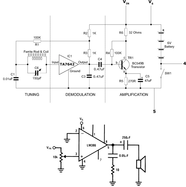
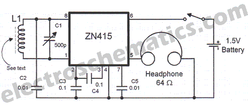
This functioning radio was built for an electronics module. The specified design was modified to include batteries, a switch, and a speaker instead of headphones. An additional amplifier circuit was required to power the speaker driver. Although not necessary,...
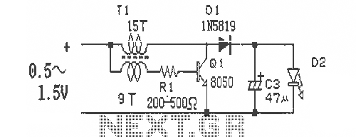
This is a simple and easy-to-build DC-DC driver circuit designed for a single flashlight battery, operating at a parametric voltage of 1.5V. The input current is 90mA, while the light-emitting diode (LED) current is 26mA or higher. The circuit...
More: The input data lacks specific content, providing only placeholders without any detailed information. In the context of electronic schematics, a comprehensive description typically involves detailing the components, their interconnections, and the overall functionality of the circuit....
The circuit described here is that of a metal detector. The operation of the circuit is based on the superheterodyning principle, which is commonly used in superhet receivers. The circuit utilizes two RF oscillators. The frequencies of both oscillators...
There are instances when a radio station can be found, and other times when no stations are detectable. The primary issue while tuning appears to be that any movement of the hands or body, such as releasing the tuning...

This circuit diagram of a digital clock utilizes six common anode seven-segment displays to indicate the time. It does not require microcontrollers or PICs for operation. The circuit operates using the MM5314 integrated circuit, functioning at either 50 Hz...