
Electronic Lock

The electronic lock circuit operates on a straightforward principle of counting and logic, utilizing a decade counter to track the sequence of correct button presses. The IC1 (4017) decade counter serves as the primary counting mechanism, where each button press generates a clock pulse that increments the counter. The design allows for a maximum of 8 sequential presses, corresponding to the digits of the passcode. The circuit's resilience against incorrect entries is further enhanced by the logic gates provided by IC2, IC3, and IC4, which ensure that any erroneous input triggers a reset, thereby safeguarding the system from unauthorized access attempts.
In terms of physical implementation, the switches S1 to S8 can be arranged in a user-friendly layout, potentially as a keypad, to facilitate ease of use. The randomization of the switch positions adds an additional layer of complexity, making it more challenging for potential intruders to guess the correct sequence. The inclusion of the reset button (S10) allows users to quickly clear the current input sequence, which is particularly useful in scenarios where an incorrect passcode is entered or if the user wishes to start over.
Overall, this electronic lock circuit exemplifies an effective balance between simplicity and security, making it suitable for various applications requiring controlled access to electronic systems. The ability to rewire the switches for altering the passcode further enhances the lock's adaptability, allowing it to meet changing security needs without significant redesign.This is a simple but efficient Electronic lock. This lock can be used to protect any electronic systems from unauthorized usage. To get access the uses needs to know 8 digit pass-code or password. When the user enters correct 8 digit password followed by "Enter" button, it activates the relay allowing access to the system controlled by relay. If t he 8 digit pass-code is incorrect, after pressing "Enter" button, the circuits reset`s itself without turning the relay on. Heart of the circuit is IC1 (4017) decade counter. At power up, the counter will be at zero count and only pin-3 of IC1 will be high. If switch S1 is pressed momentarily it will provide a clock pulse for the counter which will increment the count and move high value from one pin to another (counting pulses) < /br> For example after power-on, only pressing S1 will switch high value from pin-3 to pin-2.
After that only pressing S2 will move high value from pin-2 to pin4. Hence by pressing S1 to S8 sequentially, the high level on the pins shifts from pin-3 to 2 -> 4 -> 7 -> 10 -> 1 -> 5 -> 6-> and finally to pin-9. Only and only when ping 9 is high, pressing the "Enter" button will activate the relay and the clock will get opened.
Any wrong-entry will reset the sequence. This circuit can be intentionally reseted by pressing the "Reset" button (S10). Switches S1 to S8 can be given random display numbers, and their random placement will make it difficult to guess the pass-code ( may be placing them as 3x3 switch matrix). One or more parallel connection switches of S10 can be placed in between S1 to S8 to increase the complexity of the code, so that any random pressing will repeatedly keep reseting the circuit and not allowing any access.
IC2 (CD4071), IC3 (CD4081) and IC4 (CD4069) are used to provide logic so that the circuit gets reset if incorrect pass-code is entered. This circuit can be simplified by reducing this specific logic, which also means compromising the strength of the lock.
* NOTE : To alter the pass-code of this combination lock, you simply re-wire the switches. All the material on this website is copyright property of Material on this site is for personal use only and can not be used for any commercial activity without written permission of Use the information provided within this website at your own risk. Information within this website is provided as-is without warranty or guarantee of any kind. Please read Copyright and Disclaimer notice carefully. 🔗 External reference
Related Circuits
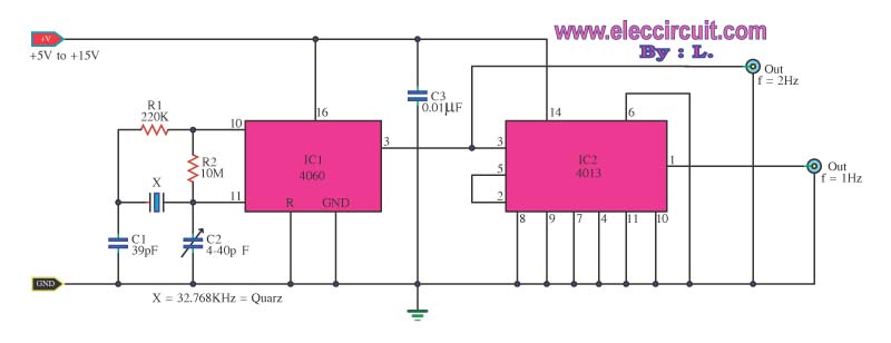
This is a standard digital clock circuit with a frequency of 1 Hz or 2 Hz. It can be utilized in a conventional clock circuit. The circuit comprises IC-4060 and IC-4013. The digital clock circuit operates by generating a precise...
Design and implementation of a TC237 CCD camera. The TC237 CCD camera is a sophisticated imaging device that utilizes a Charge-Coupled Device (CCD) sensor for capturing high-quality images. The design process involves several key components, including the optical system, electronic...
A Super GameBoy was acquired, but it has been observed that the sound pitch is significantly higher than that of an original GameBoy. This discrepancy arises due to a mismatch in CPU clock frequencies: 4.194304 MHz for the original...

The circuit is a high-power car audio amplifier schematic. It functions as a car audio amplifier using the PA02 and LH0101 integrated circuits (ICs). Each IC delivers an output power of 30W with an 8-ohm impedance. The part list...
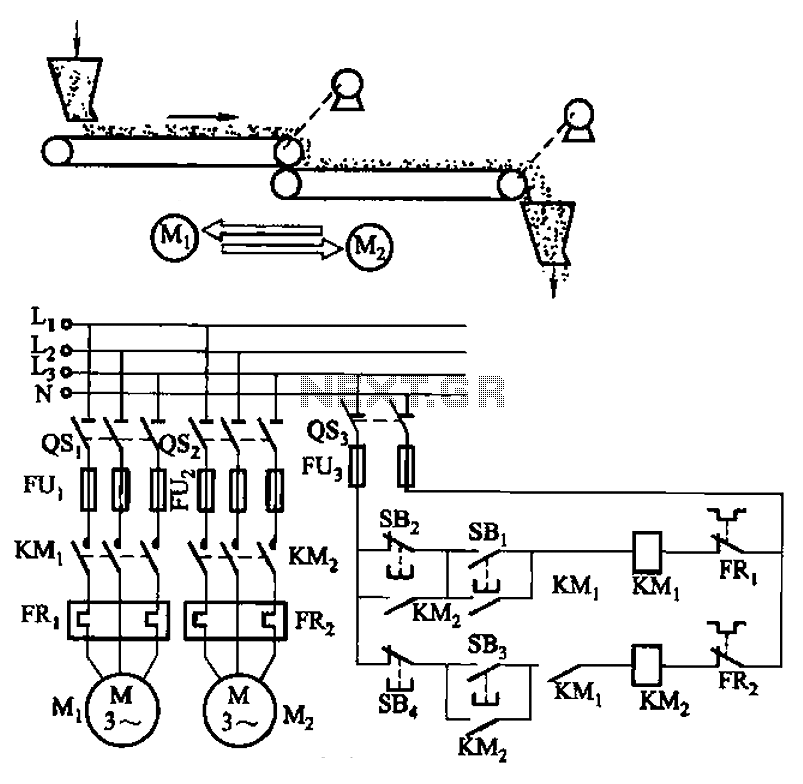
The circuit depicted in Figure 3-86 utilizes a line utilization time relay to control two motors, starting one before the other after an initial stall. The time relay KTi can be adjusted to modify the starting interval of the...
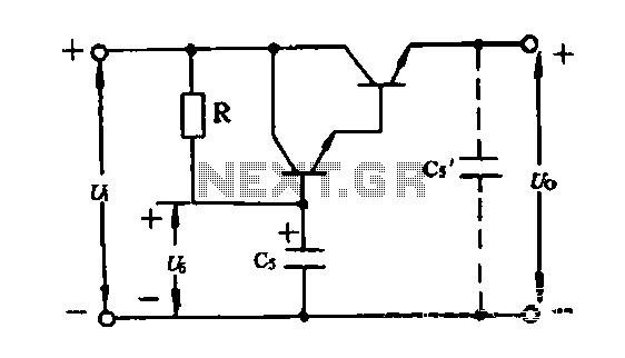
An electronic filter is utilized to enhance the filtering effect of capacitor C5. Capacitors in this configuration form a composite circuit with the electronic filter, as illustrated in the accompanying figure. The advantage of using smaller capacitors (5 to...