
underclock the Super GameBoy

To address the issue of mismatched clock frequencies between the Super GameBoy and the original GameBoy, it is essential to understand the clock circuitry within the Super GameBoy. The CPU in the Super GameBoy operates at a frequency of 4.295454 MHz, which is slightly higher than the original GameBoy's 4.194304 MHz. This difference results in a higher sound pitch, which can affect the overall gaming experience.
Underclocking the Super GameBoy requires precise modifications to the clock input circuitry. The clock signal for the CPU is typically generated by a crystal oscillator or a phase-locked loop (PLL) circuit. In the case of the Super GameBoy, the clock signal can be found on the main circuit board, usually connected to the CPU's clock input pin.
To successfully underclock the device, one approach involves replacing the existing crystal oscillator with one that has a lower frequency, ideally 4.194304 MHz. Alternatively, if the design allows, a frequency divider circuit could be implemented to reduce the clock frequency without needing to replace the oscillator. This would involve routing the clock signal through a flip-flop or a counter that divides the frequency by a specific factor.
It is critical to ensure that any modifications do not disrupt other functionalities of the Super GameBoy. Therefore, a thorough understanding of the schematic and layout of the circuit board is necessary. Additionally, testing the device after modifications will confirm whether the sound pitch has been successfully adjusted to match that of the original GameBoy.
In summary, addressing the clock frequency mismatch involves identifying the clock signal connections on the CPU and implementing a suitable method for underclocking, either through oscillator replacement or frequency division. This process requires careful consideration of the existing circuitry to maintain the integrity and functionality of the Super GameBoy.I got myself a Super GameBoy today, but I noticed that the sound pitch is notably higher than an original GameBoy(CPU clock frequency doesn`t match between the Super GameBoy and GameBoy "Brick," 4.194304 MHz for the "Brick" and 4.295454 MHz for the Super GameBoy. I`m looking to underclock the thing, but I have no clue where the clock frequency is supposed to be hooked up on the CPU.
The guide I`ve found for the GameBoy "Brick"(this one:.. 🔗 External reference
Related Circuits
The ADRF6702 TxMod is an IQ modulator that includes an integrated phase-locked loop (PLL) and voltage-controlled oscillator (VCO). The PLL synthesizer employs a fractional-N PLL to produce a 2*FLO input for the I-Q modulator. The PLL reference input can...
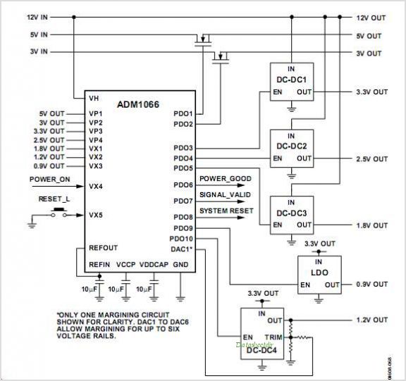
This discussion assists in selecting the most appropriate microprocessor supervisor integrated circuit (IC) for specific applications and provides solutions for various common supervisory issues encountered with microprocessors. Microprocessor supervisor ICs are critical components in ensuring the reliable operation of microprocessor-based...
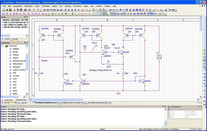
SuperSpice's philosophy is centered around the edit schematic, run simulation, view waveforms, probe signals, view waveforms, edit schematic cycle. All key issues have been automated. You can effortlessly modify the schematic, rerun and inspect new waveforms without having to...
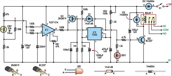
The "Super Light Sensor" is designed to respond to minor changes in light levels, automatically adjusting from approximately 200 lux to 60,000 lux, accommodating environments ranging from a dimly lit room to direct sunlight. Its applications include detecting vehicles...
The integrated circuit U1, which is an NE602 double-balanced mixer, functions as both an oscillator and a frequency mixer. Signals received from the antenna input at J1 are transmitted through a DC-blocking capacitor C1 to the RF-gain control resistor...
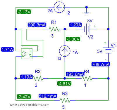
The top right node is connected to two voltage sources and contains three elements. All other nodes also have three elements. The selection of the top right node is significant because it allows for the determination of the node...