
Electronic Locker

The electronic locker circuit is designed for secure access, employing a switch matrix to input a specific code. The matrix consists of 16 switches arranged in a grid, allowing for a combination of inputs to unlock the device. Each switch corresponds to a unique row and column, creating a reliable method for user interaction. The design incorporates logic gates, specifically the 7408, to facilitate the processing of the input signals from the switch matrix. The 7414 is utilized to establish the connections necessary for identifying the correct sequence of switch presses.
The locking mechanism is controlled through a motor or inductors, providing a physical means of securing the locker. The L293D motor driver is essential for managing the power and direction of the motor, ensuring that the locking and unlocking actions are executed smoothly. The choice between using an electric motor or inductors depends on the desired mechanism's efficiency and response time.
Power management is a critical aspect of the design, with considerations made for energy conservation and battery life. The use of a 6V rechargeable battery is recommended for prolonged use, while alternative power sources, such as disposable batteries, are acknowledged for their cost-effectiveness. The inclusion of LEDs serves as visual indicators of the locker's status, enhancing user experience by providing immediate feedback on the locking mechanism's state.
Overall, this electronic locker circuit combines user-friendly design with robust security features, making it suitable for various applications where access control is paramount.This circuit is an Electronic Locker. It is controlled by a switches combination (by a code). There is a switch matrix on the door of the locker. This one is a unit of switches connected into 4 arranged of 4 columns for a total of eight terminals. When we press on a switch, this one establishes the contact between its column and its line. This swi tch matrix is also used in the telephones, for example. But it is numbered from 0 to 9 and from A to F for a total of 16 switches. To open the locker, we have to press 4 specific and different switches in the good order. If for example the code is 0, 1, 2, 3 and we press two times to the same switches: 0, 1, 2, 2, 3 the locker won`t open. In this circuit, the code is 0, 1, 2, 3 but we can set the desired code when we built de circuit. The desired line (called "stage" in the schematic) is connected to the ground and to a pin of the 3. 3k resistor and the other line is connected to an input of the 7408 and to the other pin of the resistor.
All the desired numbers of the code are in the same line. To set the order of the number of the code, we have to set the good connection between the node of the 7414 input and the appropriate node of the capacitor. For example, if we select the first line (y1) and the code is 0, 1, 2, 3 the first number (#1) is connected to the top left contact (x1).
The switch 0 is corresponding to x1/y1. These points of contact are colored in orange in the schematic. When the locker is locked, the red LED is turned on and the green LED is turned off. When the locker is opened, the red LED is turned off and the green LED is turned on. To lock the locker, we can push any of the 16 switches of the matrix. The locker is powered by a 6V source. I recommend using a 6V rechargeable battery because this one lasts a long time (at least 3 full days) and can be re-used. Otherwise, we can use four 1. 5V battery connected in serial. These least only 5 hours but are less expensive. To save energy, we can remove the red LED. When the locker is powered on, it is locked. The electric motor or the inductors close the door while a bit of time and after, stop working. When we open the locker, the electric motor or the inductors open the door while a bit of time and after, stop working.
To control the state of the door (open or lock) we can use an electric motor or a pair of inductors. If we use a electric motor, when the locker is closed, the motor turns in the anti-clockwise direction during a certain time and moves down a toothed bar. After this time, the motor stops turning and the locker remains closed. When the locker is opened, the motor turns in the clockwise direction during a certain time and moves up the toothed bar.
After this time, the motor stops turning and the locker remains opened. If we use two inductors, when the locker is closed, the second inductor works during a certain time and moves left a magnetic bar by attraction. After this time, the inductor stops working and the locker remains closed. When the locker is opened, the first inductor works during a certain time and moves right the magnetic bar.
After this time, the inductor stops turning and the locker remains opened. The buffer (L293D) who controls the motor or the inductors has two Vcc inputs and four ground connections. The both Vcc inputs must be connected to the +6V and all ground connections must be connected to the ground of the circuit.
All the parts of the circuits are placed in the rack except the DELs and the switch matrix which them, are placed on the door. 🔗 External reference
Related Circuits
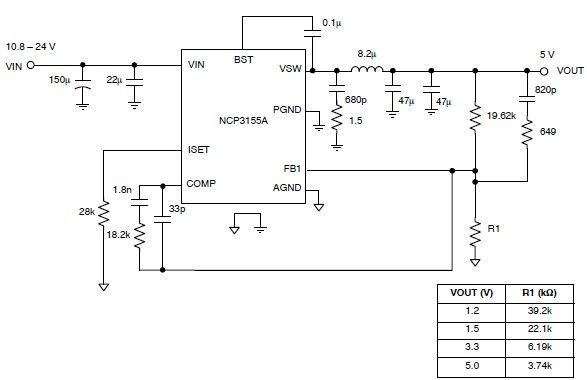
This 5-volt regulated power supply circuit project is designed using the NCP3155 DC-DC switching regulator, which features fully integrated power switches and comprehensive fault protection. The circuit requires only a few external electronic components and delivers a fixed output...
Most of the source code for this project is based on the Telecard reader project from my website. The components are few and ordinary, which means they are low-cost and easy to find. The "keys" are empty or non-telecards...
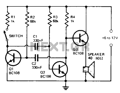
The circuit comprises a multivibrator (Q1 and Q2) and a low-power output stage (Q3). The speaker should have an impedance ranging from 40 to 80 ohms. To accommodate a low-impedance speaker, an output transformer should be connected from the...
This circuit is a modified Hartley oscillator that incorporates additional components. The transformer used is a small audio transformer, specifically type LT700. The primary winding is center-tapped with an impedance of 1 kΩ at 1 kHz, while the secondary...
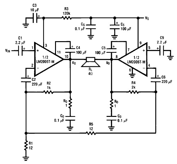
A simple 20-watt amplifier electronic project can be designed using the LM2005 dual high-power amplifier, which is engineered to provide optimal performance and reliability for automotive applications. The LM2005 20-watt amplifier has a high current capability of 3.5A, allowing...
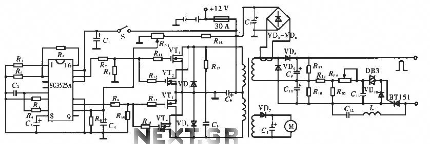
The circuit utilizes the SC3525A, a PWM silicon chip from US General Semiconductor. It features an error amplifier with an inverting input at pin 1. Pin 2 serves as the non-inverting input for the error amplifier. Pins 5 and...