
Electronic Locks Circuits

The circuit operates primarily on a microcontroller-based architecture, leveraging the capabilities of the Atmel AVR series. The AT90S2313 or ATtiny2313 microcontrollers serve as the central processing unit, executing the programmed instructions to manage user inputs and control the locking mechanism. The user interface is facilitated through a 3x4 matrix keypad, allowing for easy code entry and modification. The initial setup phase, indicated by the presence of a jumper, ensures that the device is configured to a default state, simplifying the initial user experience.
The relay serves as the primary actuator, connecting the power supply to the electromagnetic strike upon successful code entry. The timing mechanism is critical, as the system must ensure that the relay remains engaged only for the specified duration to prevent unauthorized access. The use of a beeping sound provides auditory feedback to the user during the setup phase, enhancing usability.
For additional flexibility, the circuit can be adapted to control various devices beyond just door locks. The combination lock functionality is particularly versatile, allowing for the integration of a range of outputs, such as garage doors, alarms, and other electronic devices. The optional LCD display can provide visual feedback, displaying messages or prompts to the user, although the core functionality remains intact without it.
The electronic locker design emphasizes security through the use of a switch matrix, which can be configured to require multiple inputs for access, further enhancing the security of the stored items. The incorporation of telecards in the safety lock design introduces a modern approach to access control, enabling the registration and deregistration of keys, which can be particularly useful in shared environments.
Overall, this circuit design represents a comprehensive solution for electronic locking mechanisms, with applications extending across various domains, from residential to commercial use. The modular nature of the design allows for easy customization to meet specific user requirements, making it a valuable addition to any security system.This circuit can be used to operate an electric strike or an electromagnetic lock on a door. It is not the door being opened/closed, but a small electromagnetic strike which unlocks the door. The opener has the following features currently programmed in software. (schematic) Code Lock with ATMEL AVR - Code Lock AVR electronic combination lock is realized with Atmel AVR microcontroller AT90S2313 or ATtiny2313. Program in hex code is 2 kB long. User code is consisted of 1 to 4 digits. If you buy the chip than user code is consisted of 1 to 8 digits. If the code is entered in the correct sequence, then after 1 second the relay and the electric striker (in the door) switch on for 1 second and then switch off again. User code can be changed via 3x4 matrix keypad. Keypad for CodeLock can be bought at local electronic shop. Initial user code (1234) is set up with a jumper. The jumper must be inserted before the voltage (12V) connection. The jumper must be removed after 2 beeps (after 5 to 15 seconds). . (circuit design) Combination Digital Lock - A multiple input combination lock using CMOS counter IC`s.
Flexibility and code change is allowed by changing output connections. (schematic / circuit design) Combination lock - Operate your gate or something different by this simple electronic combination lock. The combination can have a chosen length of numbers or alphabets, and can be changed any time. The LCD display is optional, the circuit works fine without it. After entering the correct combination, a relay is operated for the predefined time. (design) Combination Lock (nutchip) - Combination lock are nice to enable alarms, but are useful for controlling a wide range of electric devices.
These software keys can open gates, garages, TV sets, telephones, VCRs, well pumps. In practice this circuit is capable to lock or time all the devices that can be connected to relays. (electronic design) Electronic Lock - This is my electronic combination lock to use with an outdoor gate. The functionality is implemented in software. It turns on a relay (usually to open a door) for a few seconds . Uses a PIC16F84A (circuit) Electronic Lock (Bill Bowden) - The digital lock shown below uses 4 common logic ICs to allow controlling a relay by entering a 4 digit number on a keypad.
The first 4 outputs from the CD4017 decade counter (pins 3, 2, 4, 7) are gated. Electronic Lock circuitdb - The digital lock shown below uses 4 common logic ICs to allow controlling a relay by entering a 4 digit number on a keypad. The first 4 outputs from the CD4017 decade counter (pins 3, 2, 4, 7) are gated. Electronic Locker - This circuit is an Electronic Locker. It is controlled by a switches combination (by a code). There is a switch matrix on the door of the locker. This one is a unit of switches connected into 4 arranged of 4 columns for a total of eight terminals.
(circuit design) Electronic Safety Lock Based on Attiny26 - This safety-lock can be work with up to 8 different telecards (empty or not) as access keys. Each tele card can be registered or unregistered fromthe system, by press the corresponding button. (electronic circuit) iButton electronic lock Circuit - This electronic lock can be used with any type of iButtons you may already have, since the only thing needed is the internal serial number, that`s different for every iButton .
(circuit diagram) Infrared gate 2 (Peter Jakab) - This is an infrared gate with two sensors planned to use in the wall in the way behind a door. It can be applied in a toilet to keep track of that someone is inside exceeding a certain amount of time.
After that time elapsed, the circuit triggers the digital output which can turn on a ventilator. The time period. (electronic circuit) Simple combination lock - This experiment may be built using only one 8-position DIP switch, but the concept is easier to understand if two switch asse 🔗 External reference
Related Circuits
The circuits in Figure 1 and Figure 2 demonstrate specific advantages over the circuit presented in the Design Idea in EDN, titled "Circuit detects first event," published on May 3, 2001, page 89. The n-player first-event detection circuit provides...
For the shorter wavelength VHF and UHF bands, it is more practical to construct complex antennas such as a single-band Slim Jim or Yagis. Various projects include creating an electronic unit, as it is necessary for the Intermediate Level...
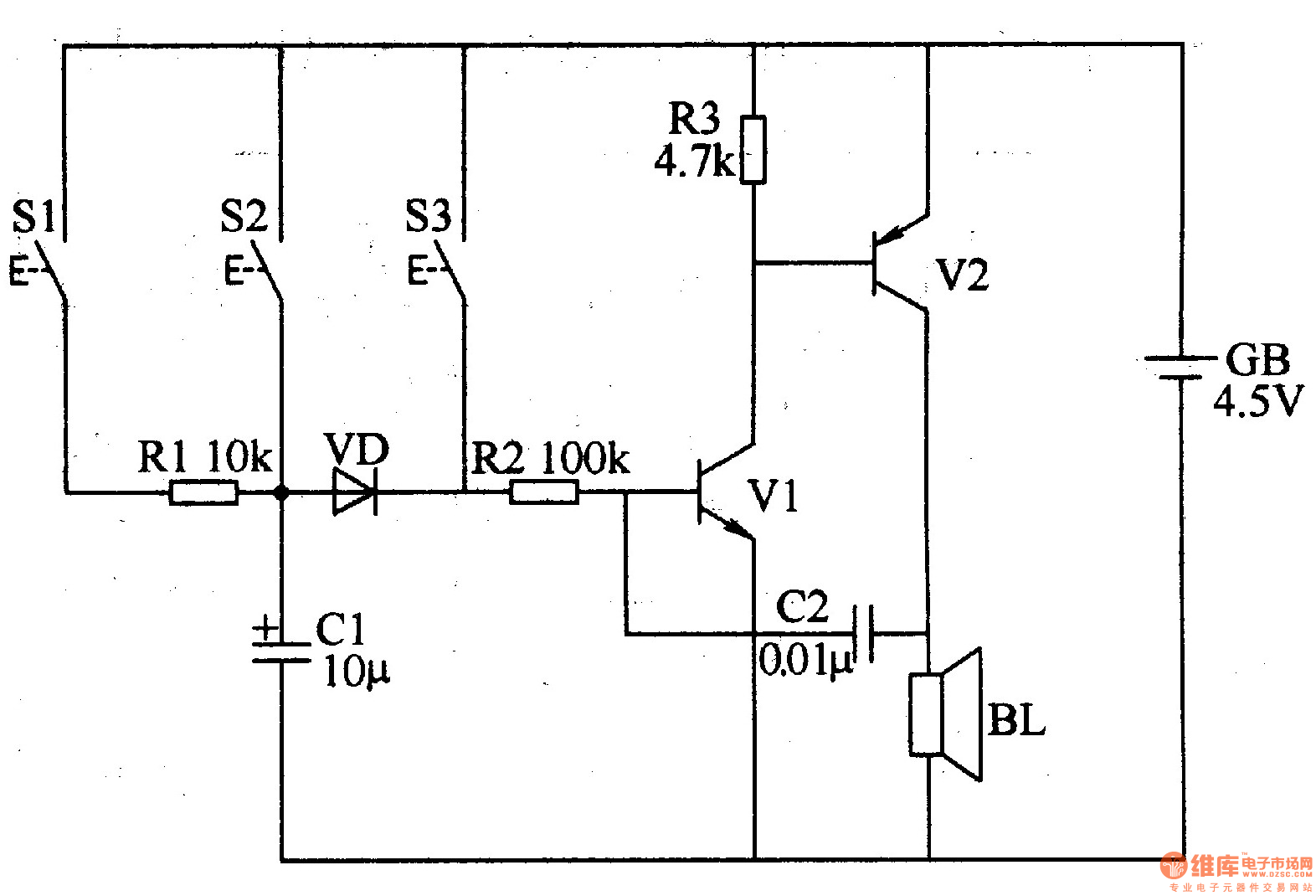
The three-tone electronic doorbell circuit includes buttons S1-S3, transistors V1 and V2, a speaker BL, resistors R1-R3, capacitors C1 and C2, a diode VD, and a battery GB, as illustrated in Figure 3-109. Resistors R1-R3 are 1/4W carbon film...
This audio noise filter circuit is a bandpass filter designed for the audio frequency range. It effectively filters out unwanted signals that fall outside the audio frequencies. The circuit consists of two filters: a low-pass filter and a high-pass...
An advantage of a photogate over a sound trigger is that the former activates based on the exact position of the object that interrupts the beam. For instance, the shape of a snapped elastic cord can be captured as...
These two tank circuits appear to broaden the operating spectrum. The accompanying information sheet indicates that when both circuit stages oscillate at the same frequency, the power output reaches its maximum. This suggests that if the tunable tank circuit...