
Electronic Music Maker

The electronic music maker operates on the principle of an astable multivibrator configuration, which generates a continuous square wave output. The frequency of this output is determined by the resistive and capacitive components connected to the circuit, as well as the resistance of the photocell, which varies with light intensity.
In this design, the photocell (light-dependent resistor, LDR) serves as a variable resistor that changes its resistance based on the amount of ambient light it receives. When light falls on the photocell, its resistance decreases, allowing more current to flow through the circuit. This change in current alters the timing components of the astable oscillator, effectively modifying the frequency of the output tone.
The schematic typically includes a power supply, which may be a battery or a DC power source, connected to the astable oscillator circuit. The circuit consists of two resistors, a capacitor, and the photocell. The output from the oscillator can be connected to a speaker or a piezo buzzer to produce sound.
Enclosing the circuit in a box allows for portability and ease of use, while also providing a way to shield the components from external light sources and interference. The design can be enhanced by incorporating additional features such as a potentiometer for manual control of the frequency, or an LED indicator that responds to the output tone.
This electronic music maker is not only an engaging project for hobbyists but also serves as an educational tool to demonstrate the principles of light sensing and sound generation through electronic circuits. This electronic music maker uses an astable oscillator circuit that is controlled by a photocell. The light falling on the photo cell controls the tone. By mounting the circuit in a box, you can control light-reading PCI with your hand.
Related Circuits
The DC motor drive controller can control two DC motors of varying current or voltage ratings, depending on the relay specifications. The circuit includes two shaft encoders that provide positional feedback to a computer. The motor control circuit connects...

A practical amplifier circuit. An electronic amplifier is a device that increases the power of a signal. It accomplishes this by drawing energy from a power supply and adjusting the output to correspond to the input signal shape, albeit...
The controllable multivibrator, as illustrated in figure 14-40, consists of a 555 timer along with resistors RA, RP1, and capacitor C1. The oscillation frequency is influenced by the control voltage applied to pin 5. This control voltage is determined...
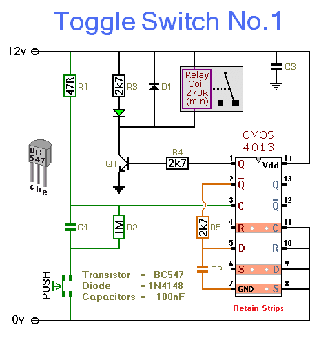
This simple circuit will energize and de-energize a relay with the push of a button. Pressing the button once will energize the relay, while pressing it a second time will de-energize the relay. The accompanying circuit provides a solid...
This power supply utilizes a single 7812 IC voltage regulator along with multiple external pass transistors, enabling it to deliver output load currents of up to 30 amps. The circuit design incorporates a 7812 linear voltage regulator, which is...
The integrated circuit (IC) is a quad 2-input "AND" gate, specifically a CMOS 4081. These gates output a HIGH signal only when both inputs are HIGH. When the key connected to pin E is pressed, current flows through resistor...