
Electronic Toggle Switch No1 circuit

The described circuit utilizes a CMOS 4013 dual D-type flip-flop to control the state of a relay based on a momentary push-button input. The circuit operates in a bistable mode, allowing it to toggle between two states: energized and de-energized.
When the push button is pressed, it triggers the clock input of the first flip-flop within the CMOS 4013. This clock pulse changes the output state of the flip-flop from low to high, energizing the relay. The relay can then be used to control larger loads or switch other circuits. When the button is pressed again, another clock pulse is generated, which toggles the output of the flip-flop back to low, thus de-energizing the relay.
Key components of the circuit include:
1. **CMOS 4013**: This IC contains two D-type flip-flops, which are the core of the toggle mechanism.
2. **Push Button**: A momentary switch that provides the clock signal to the flip-flop.
3. **Relay**: An electromagnetic switch that is actuated by the output of the flip-flop.
4. **Resistors and Capacitors**: These may be included for debouncing the push button and ensuring stable operation of the flip-flop.
The circuit can be powered by a suitable DC source, typically between 3V to 15V, depending on the specifications of the relay and the CMOS IC. Proper attention should be given to the relay's coil voltage and current ratings to ensure compatibility with the circuit design.
In summary, this circuit effectively demonstrates the basic principles of digital electronics and relay control, making it a valuable learning tool for those interested in electronics and circuit design.This simple circuit will energize and de-energize a relay at the push of a button. Pushing the button once - will energize the relay. And pushing it a second time - will de-energize the relay. The accompanying Circuit offers a good introduction to the workings of the Cmos 4013.. 🔗 External reference
Related Circuits

A diode, such as the IN4148, has a typical temperature coefficient of -2 mV/°C at a 1 mA diode current. Transistors Q1 and Q2 form a constant current source. Diode D1 serves as the temperature sensor. Integrated circuits ICl-a...

The circuit utilizes IC1 to create an astable multivibrator configuration. It is designed to generate a low-frequency output of approximately 1 Hz at pin 3, which is determined by the resistor values R1, R2 and capacitor C1. The output...

I designed up this circuit board because of a request from a visitor to my website. I also assemble the circuit board to verify the board was correct. It does work, very nicely, but I have no way to...

The circuit features a broadband video amplifier with a 50-ohm input/output impedance. To ensure optimal signal transmission and minimize reflected signals, it is often necessary to match the input and output impedances of the amplifier. The broadband video amplifier...
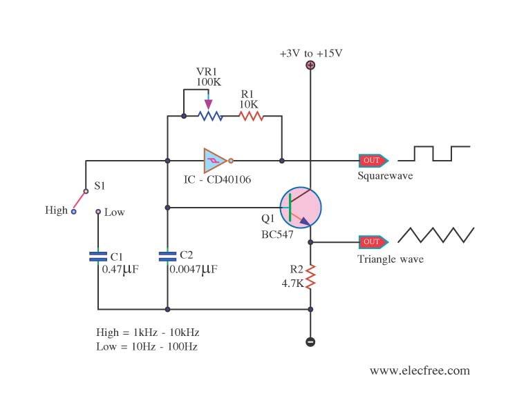
This is a function generator project that can be used as a triangle and square wave generator. The main components include the CD40106, a popular CMOS integrated circuit, and a standard transistor. The function generator circuit utilizes the CD40106, which...
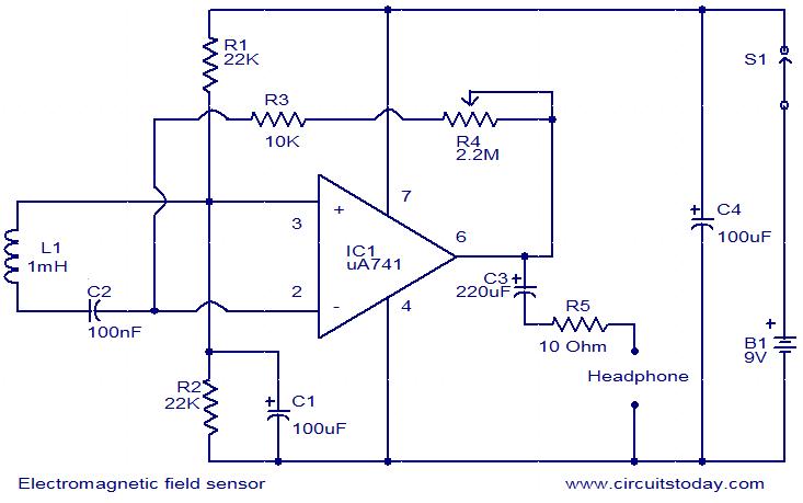
This is a very simple circuit that can be used to sense electromagnetic radiations. The circuit can even detect hidden wires. A 1mH inductor is used for sensing the electric field. The electric field will induce a small voltage...