
Electronic Roulette wheel with 20 LEDs and with 36 LEDs

The electronic roulette wheel circuit integrates several key components to create an engaging and interactive experience. The 555 timer operates in astable mode when the "Spin" button is pressed, generating a continuous pulse signal. This signal is fed into the decade counter (DD2), which counts the number of pulses and sequentially activates the LEDs. The arrangement of LEDs in strings allows for a visual representation of the roulette spin, where the illumination of each LED simulates the ball landing on a number.
The D-type flip-flop (IC 4013) is crucial for controlling which string of LEDs is illuminated. By implementing a divider by two, the circuit can alternate between two sets of LED strings, enhancing the visual effect of the roulette game. The resistors R6 and R7 play a protective role, ensuring that the outputs of the flip-flop do not exceed the rated current, thus preventing damage to the components.
The gradual decrease in frequency, when the button is released, is achieved through the charging and discharging behavior of capacitors C2 and C3. The design leverages the RC time constant, where the discharge path through resistors R2 and R3 determines the rate at which the capacitor discharges. This unique feature adds a dynamic element to the game, as the slowing illumination of the LEDs mimics the deceleration of a real roulette wheel.
In the second circuit configuration, the design expands to accommodate more LED strings. By utilizing a second decade counter instead of a flip-flop, this version can control a larger number of LEDs, enhancing the gameplay experience. The inverters (DD4.1 to DD4.4) allow for further manipulation of the signals, ensuring that the LEDs can be lit in a controlled manner, maintaining the integrity of the roulette simulation.
Overall, the electronic roulette wheel circuit combines timing, counting, and LED control to create an engaging visual display that simulates the experience of a traditional roulette game. The thoughtful integration of components ensures reliable operation and enhances the user experience through dynamic lighting effects.In this electronic roulette wheel (see Fig. 1. ) the timer 555 works as a generator of pulses with fading frequency. The counter 4017 switches LED`s one by one in the selected string, and the divider by two based on D-type flip flop (4013 IC) selects the LED`s strings. Actually the base of this circuit diagram is the counter DD2 and the string of L EDs D1. D10 (if we connect the resistor R6 to the ground and remove the D-trigger and LEDS DD11. DD20 from the circuit then we get simple electronic roulette wheel with 10 light-emitting diodes), so by adding a D-trigger to the circuit we can add more LED`s. When the button SB1 ("Spin") is first pressed and then released, the generator produces pulses with frequency that getting lower, and at the end the generator stops.
The decade counter DD2 counts this pulses, and the state of its outputs changes with every pulse. The light emitting diodes is connected in tho strings D1. D10 or D11. D20 lights up one by one (it looks like it "spins"). At the end an only one LED will illuminate. It is imitate a roulette spin. The DD3 divider by two changes its state every 10 pulses, and this divider selects the first or the second string of LEDs. Resistors R6, R7 prevents overload of outputs of DD3 flip flop trigger. All inputs of the second flip flop of IC DD3 should be grounded. The 555 integrated circuit produces pulses. When the power switch SA1 is on and the button SB1 is pressed then the frequency of the timer is constant.
When the button SB1 is released then the frequency of the timer will slowly fading down. The capacitor C2 was charged while the button SB1 was pressed, so now C2 discharges through resistors R2, R3, capacitor C3 and the output "DIS" ("discharge") of the 555 IC. Because the current that charges the capacitor C3 getting weaker, it takes more time to charge the capacitor C3 to the voltage of activating the trigger of the timer.
So the frequency of the 555 timer will fading down. When this voltage at the capacitor C2 gets reduced below the trigger level then the timer will stopped. The second circuit diagram (see Fig. 2. ) reminds the first one. It uses four strings of 9 light emitting diodes in each one string, and instead on D-type flip flop trigger it uses the second decade counter.
The outputs of the counter are connected to the inverters DD4. 1. DD4. 4. 🔗 External reference
Related Circuits
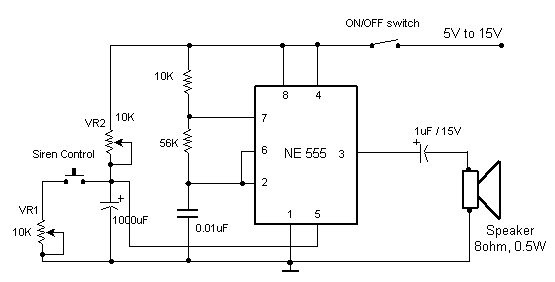
This circuit produces a sound similar to a factory siren. It makes use of a 555 timer IC used as an astable multivibrator of a center frequency of about 300Hz. The frequency is controlled by pin 5 of the...
The following file is an application note describing the two stages of an electronic ballast for a 250 W HID metal halide lamp. The components include. The application note outlines a two-stage electronic ballast designed specifically for a 250 W...
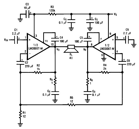
A simple 20-watt amplifier electronic project can be designed using the LM2005 dual high-power amplifier, which is engineered to provide optimal performance and reliability for automotive applications. The LM2005 20-watt amplifier has a high current capability of 3.5A, allowing...
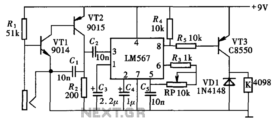
The electronic lock circuit is based on the frequency characteristics of the LM567 audio decoder. This circuit utilizes the audio decoding feature of the LM567, which outputs a low signal when the input signal frequency matches the oscillation frequency...
This circuit causes an LED to blink every half second. The duration of the blinking can be modified by changing the value of capacitor C1. Additionally, up to 18 more LEDs can be connected to this circuit, allowing for...
When button S12 is pressed, a positive voltage supplied through resistor R1 is applied to the base of transistor Q1, activating it. When Q1 is in the conducting state, pin 1 of U1 is connected to ground (low) or...