
flash light electronic diagram

The circuit functions as a basic LED flasher using an astable multivibrator configuration, typically implemented with a 555 timer IC. The blinking frequency is determined by the resistor and capacitor values in the circuit. In this setup, capacitor C1 plays a crucial role in timing; its capacitance value directly influences the charge and discharge cycle, thereby adjusting the blinking interval.
The primary components of the circuit include:
- A 555 timer IC configured in astable mode.
- Resistors (R1 and R2) that set the timing intervals along with capacitor C1.
- A series of LEDs connected in parallel to the output of the 555 timer, with appropriate current-limiting resistors to prevent excessive current flow that could damage the LEDs.
To achieve the desired blink rate, the following formula can be utilized:
\[ f = \frac{1.44}{(R1 + 2R2) \times C1} \]
Where \( f \) is the frequency in hertz, \( R1 \) and \( R2 \) are the resistances in ohms, and \( C1 \) is the capacitance in farads. Adjusting the values of R1, R2, or C1 will modify the blink rate.
For applications requiring multiple LEDs, the circuit can accommodate additional units, ensuring that the total current does not exceed the output capacity of the 555 timer. It is advisable to use a transistor to drive larger numbers of LEDs, as the 555 timer can typically source or sink a maximum of 200 mA.
In summary, this circuit provides a simple and effective method for creating a blinking LED effect, with the flexibility to expand the number of LEDs used, making it suitable for various decorative or signaling applications.With this circuit, the LED blinks every half second. How long the blink time is, can be adjusted by adjusting the value of capacitor C1. Up to 18 additional LEDs can be attached to this circuit (36 LEDs total). 🔗 External reference
Related Circuits

Before getting started, an acknowledgment is due. The circuit presented here employs an innovative method of controlling a flyback converter using the voltage developed across a current-sensing resistor. This approach was published by Andrew Armstrong in the July 1992...

Tired of always spending money on flashlight batteries only to have them fail just when you need them? Try this simple circuit out. It would make an excellent science fair project. The white LEDs are quite bright, they provide...
This is basically a flasher circuit modified to turn on and off a bulb instead of a LED. It uses a 555 timer IC working as an astable multivibrator. The flashing rate can be varied from very fast to...

Any type of flashing light on the main brake lights is prohibited and illegal in most states of the U.S.A. Verification is being conducted for the same in Canada. Meanwhile, using this circuit is at one's own risk, with...
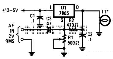
In the visible-light transmitter, a 7805 voltage regulator is configured in a variable-voltage setup, with an audio signal input to modulate the output voltage. The modulated output voltage is utilized to transmit information through an incandescent lamp. The visible-light transmitter...
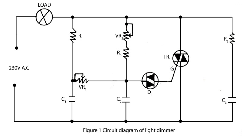
The lighting source, such as a bulb or tube light, illuminates based on its specified wattage. To achieve increased brightness, a higher wattage bulb must be used, while a lower wattage bulb is necessary for reduced brightness. However, it...