
Circuit Diagram for 250 W HID Metal Halide Electronic Ballast

The application note outlines a two-stage electronic ballast designed specifically for a 250 W high-intensity discharge (HID) metal halide lamp. This ballast serves to regulate the electrical power supplied to the lamp, ensuring optimal performance and efficiency.
The first stage of the ballast typically involves a power factor correction circuit, which enhances the efficiency of the power supply. This stage may include components such as inductors, capacitors, and rectifiers that work together to convert the AC input voltage into a more stable DC voltage. The power factor correction stage is crucial for minimizing energy losses and improving overall system performance.
The second stage of the ballast is responsible for providing the necessary starting voltage and operating current to the metal halide lamp. This stage may utilize a high-frequency inverter circuit, which converts the DC voltage back into a high-frequency AC signal. The inverter is composed of various electronic components, including transistors or MOSFETs, which switch on and off at a high rate to generate the required output frequency. The output stage may also include a transformer to step up the voltage to the level required for ignition and sustained operation of the lamp.
In addition to the core components, the application note may detail various protective features integrated into the ballast design, such as overcurrent protection, thermal management strategies, and fault detection systems. These features are essential for ensuring the longevity and reliability of the ballast and the HID lamp.
Overall, the electronic ballast is a critical component in the operation of HID metal halide lamps, providing the necessary electrical characteristics to ensure efficient lighting performance while maintaining safety and reliability in various applications.The following file is an application note describing the two stages of electronic ballast for a 250 W HID metal halide lamp. The components include.. 🔗 External reference
Related Circuits
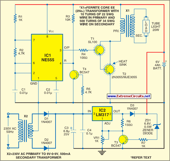
The circuit consists of inverter and charger sections. The inverter section utilizes the NE555 timer, while the charger section is based on the LM317 adjustable regulator. In the inverter section, the NE555 is configured as an astable multivibrator, generating...
When the comparator's output transitions from low to high, the rising edge of the output pulse, differentiated by the Cl/Rl chain, activates Ql. This action blocks the comparator via its strobing input and maintains its output state for a...
The EUA2032 is a high-efficiency, 2.5W mono class-D audio power amplifier. A newly developed filterless PWM modulation architecture further reduces EMI and THD+N, as well as eliminates the LC output filter, thereby reducing the external component count, system cost,...
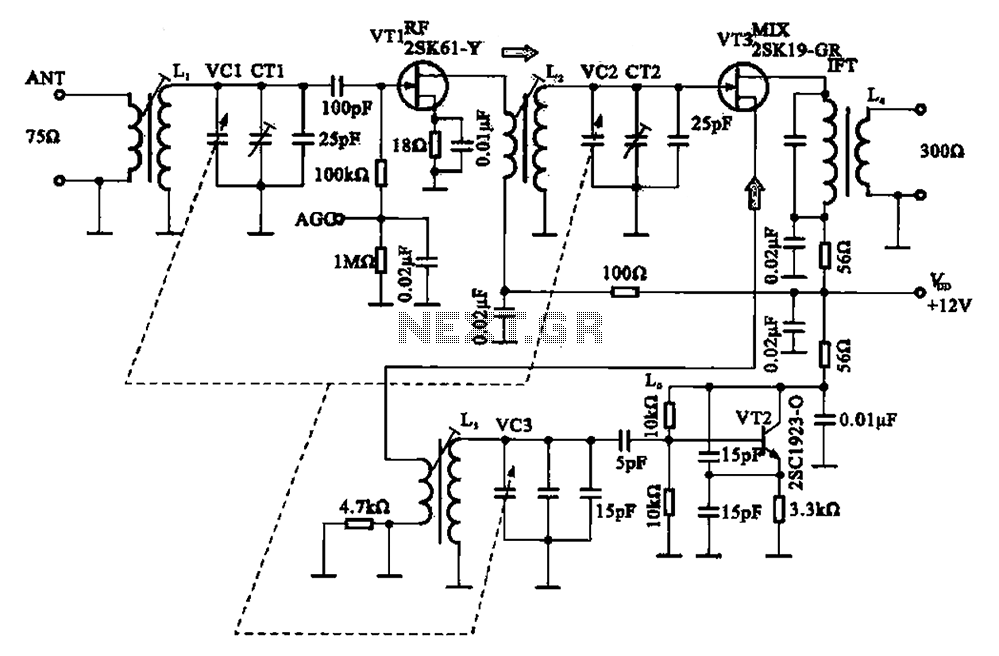
The FM radio circuit consists of a high-frequency amplifier (VT1), a mixer and local oscillator (VT2), and additional components. The circuit includes an FM radio antenna for signal detection, with an input transformer (L1) connected to a gate transistor...
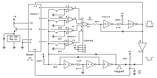
The digital lock shown below uses 4 common logic ICs to allow controlling a relay by entering a 4 digit number on a keypad. The first 4 outputs from the CD4017 decade counter (pins 3,2,4,7) are gated together with...
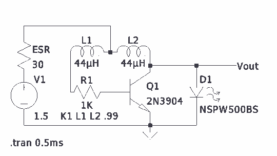
There is much pleasure in useless knowledge. The value of the inductors (44 µH) was determined using an online toroid calculator, specifying an FT-50-43 toroid with 10 turns through it. The described circuit involves the use of an FT-50-43 toroidal...