
Electronic Siren Circuit

The DIY Electronic Siren circuit is designed to generate three recognizable siren sounds that mimic those of police, ambulance, and fire engines, making it versatile for various applications, including toys and alarm systems. The circuit's functionality relies on a simple switch mechanism (S1) that allows users to toggle between different siren sounds, enhancing the interactive experience in toy models or providing auditory alerts in security systems.
The choice of transistors is crucial for optimizing sound output. The BC337 transistor is suitable for driving a small loudspeaker (200 mW) in lower power applications, drawing around 140 mA from a 9 V power source. For applications requiring higher sound levels, the BD136 is recommended, as it can handle a 5W loudspeaker with a current draw of approximately 180 mA from a 12 V supply. This transistor's capability to drive larger speakers makes it ideal for projects where sound intensity is a priority.
In scenarios where maximum volume is desired, the circuit can be expanded to include a second output stage. The BD136 can serve as the initial driver, while a more powerful transistor, such as the AD162 or MJ2955, can be employed to drive a 15W loudspeaker. This configuration significantly increases the sound output, with peak current consumption reaching about 500 mA when powered by a 12 V supply. It is essential to ensure proper cooling for the output transistor to prevent overheating during prolonged use.
Additionally, the design includes considerations for power supply efficiency. Capacitor C1 is not required when operating on batteries, simplifying the circuit design for portable applications. This flexibility allows the DIY Electronic Siren circuit to be customized for various needs, whether in toy design or as part of a larger alarm system, making it a valuable addition to any electronics engineer's toolkit.The DIY Electronic Siren circuit described here can create three different US-style siren sounds: DIY police, DIY ambulance and fire engine. The desired sound can be selected using switch S1. The circuit can be used in toys (such as model vehicles), as part of an alarm system, and in many other applications.
For use in a toy, a BC337 is an adequat e device for driver T5, since it is capable of directly driving a 200mW (8 ©) loudspeaker. In this case the current consumption from a 9 V power supply is around 140 mA. If a louder sound is required, a BD136 is recommended: this can drive a 5W (8 ©) loudspeaker. The current consumption of the electronic siren from a 12 V supply will then be about 180mA. If still more volume is desired, then T5 (a BD136) can be used as a first driver stage, and a 15W (8 ©) loudspeaker can be connected via output transistor T6. Here an AD162 or an MJ2955 can be used, which, for continuous operation, must be provided with cooling.
The peak current consumption of the circuit will now be about 500mA with a 12V power supply. Capacitor C1 is not required for battery operation. 🔗 External reference
Related Circuits

This circuit is a low-noise preamplifier designed for the 435-MHz amateur satellite frequencies. It utilizes a Mitsubishi MGF1302 transistor. A 28-Vdc power source is indicated; however, lower voltages can be employed by adjusting the 400-5-W resistor. The low-noise preamplifier circuit...
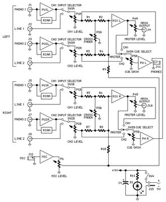
The mixer circuit features two line inputs and two microphone inputs, along with two line outputs. The microphone inputs are designed for low-impedance dynamic microphones with an impedance range of 200-1000 ohms. This simple mixer was specifically designed to...
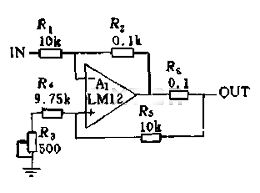
In a servo system, the current drive connection is frequently utilized. The output current (IOUT) is proportional to the input channel number (y). Using the current drive mode can mitigate issues caused by the motor's large inductance, which induces...

The preamplifier circuit is designed to offer appropriate loading for phono cartridges with reluctance. It achieves a gain of approximately 25 dB at 1 kHz (converting an input of 2.2 mV to an output of 100 mV). The circuit...

The circuit employs a widely used Sharp IR module (the Vishay module may also be utilized). The pin numbers indicated in the circuit pertain to both the Sharp and Vishay modules. For other modules, it is recommended to consult...
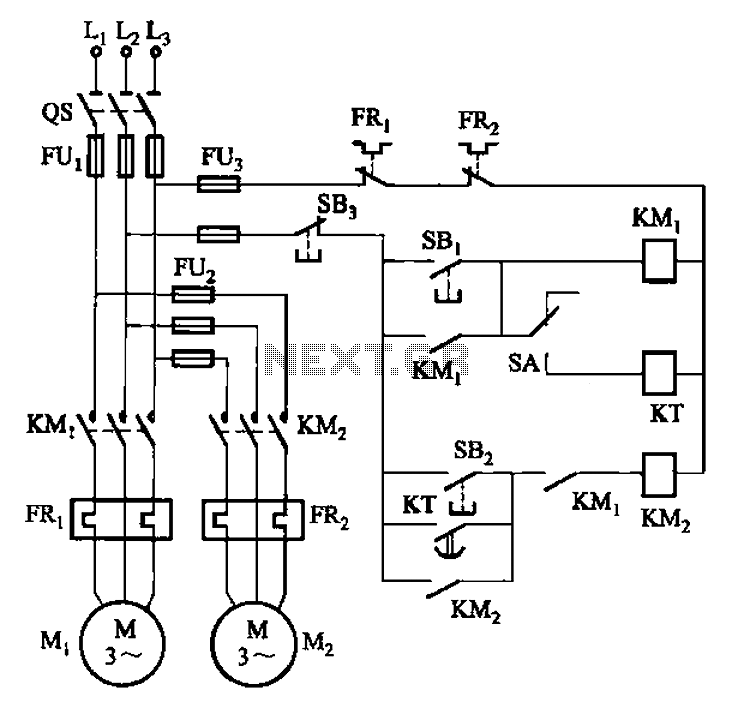
The circuit illustrated in Figure 3-85 features both manual and automatic control through the transfer switch SA. After initiating the motor Mi, an automatic start sequence is achieved via the time relay KT. The circuit employs a transfer switch (SA)...