
Two electric motors has started manual and automatic control circuit

The circuit employs a transfer switch (SA) that allows for both manual and automatic operation modes. In manual mode, an operator can directly control the motor Mi, initiating it as needed. The automatic mode is facilitated by the time relay (KT), which is programmed to activate the motor after a predetermined delay. This feature is particularly useful in applications where a delay is required to ensure that certain conditions are met before the motor starts.
The motor Mi is connected to a power supply through the transfer switch, which can be toggled based on the desired mode of operation. When the automatic mode is selected, the time relay KT begins its countdown as soon as the circuit is powered. Upon completion of the countdown, the relay closes its contacts, allowing current to flow to the motor Mi and thereby starting it.
The circuit design may also include additional protective elements such as fuses or circuit breakers to safeguard against overload conditions. Furthermore, status indicators may be integrated to provide visual feedback regarding the operational state of the motor, whether it is running, idle, or in a fault condition.
Overall, this circuit configuration is beneficial in applications requiring flexibility in operation, enabling both manual intervention and automated control based on specific timing requirements. Circuit shown in Figure 3-85. Manual and automatic control through the transfer switch SA. After starting the motor Mi, to start. Automatic start sequence by time relay KT to a chieve.
Related Circuits
A high voltage power supply DC converter that operates between 3V to 500V has been suggested for use with Geiger tubes. However, during simulation, the output remained at nearly 9V, which matches the input voltage. The schematic drawn has...
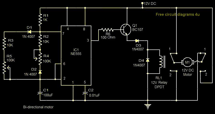
This circuit illustrates a bi-directional motor control circuit utilizing the NE555 integrated circuit (IC). Features include a 12V DC power supply, with the IC employed to control relay RL1. The bi-directional motor control circuit designed with the NE555 IC allows...
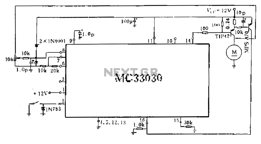
An alternative approach involves obtaining a motor's counter electromotive force from the motor end of the related signal after it has been amplified and averaged across three pins. The drive output A functions as a single-ended output, which controls...
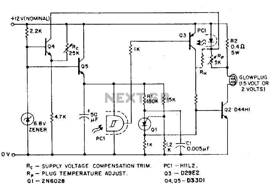
The circuit is designed for model airplanes, boats, and cars that utilize glow plugs for their miniature internal combustion engines (ranging from 0.1cc to 15cc). These engines are equipped with heavy batteries, high-tension coils, and capacitors necessary for classic...
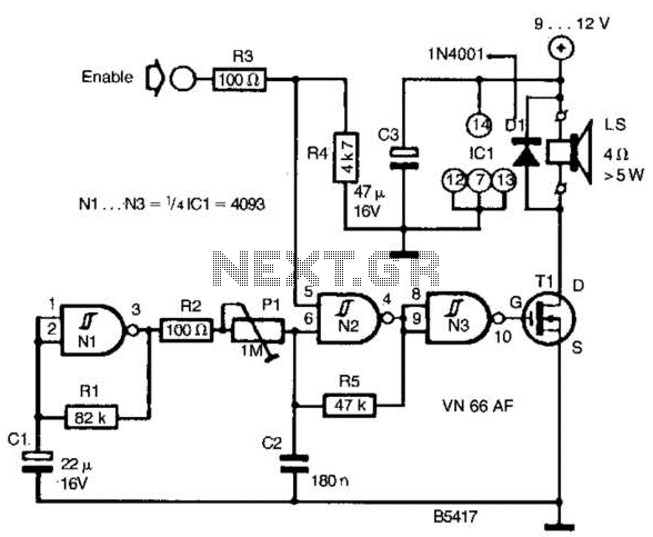
A CD4093 chip and several components form a siren oscillator that drives power MOSFET Tl. A speaker is directly powered by this device. The siren is activated by a logic high signal applied to the ENABLE input. The circuit comprises...
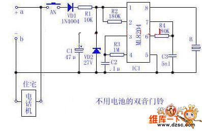
Utilize the 48V (60V) DC feedback electric current supplied by the phone feedback line as the operational energy source for the electronic doorbell, which is highly economical and practical. This document introduces a two-tone doorbell circuit that operates without...