
Electronic Tachometer

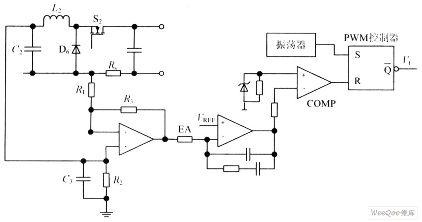
The electronic tachometer frequency converter circuit is designed to accurately measure the rotational speed of a mechanical system by converting an input signal—typically derived from a rotating shaft—into a proportional output current. This output current is then utilized to drive a pointer device, such as a galvanometer or an analog meter, which visually indicates the speed of rotation.
The circuit generally consists of several key components, including a sensor to detect the rotational speed, an analog-to-digital converter (ADC) for signal processing, and an operational amplifier (op-amp) to amplify the resulting current signal. The sensor may be a Hall effect sensor or a photoelectric sensor, which generates a pulse signal corresponding to the rotational speed.
The input signal is fed into the ADC, which converts the analog signal into a digital format for processing. The conversion process is crucial for accurate speed measurement, as it allows for precise calculations based on the input frequency. The processed signal is then sent to the op-amp, which amplifies the current to a level suitable for driving the pointer device.
The output current is designed to be linear with respect to the input frequency, ensuring that the pointer device provides an accurate and proportional representation of the rotational speed. The calibration of the circuit is essential to ensure that the readings are precise and reliable, often requiring adjustment based on the specific application and sensor characteristics.
Overall, this circuit is widely used in various applications, including automotive engines, industrial machinery, and any system where monitoring rotational speed is critical for performance and safety.The basis of the electronic tachometer frequency converter circuit-current, which converts the input signal into a proportional current measured pointer device 🔗 External reference
Related Circuits
This circuit utilizes a synthesized sound chip from Holtek, the HT-2811, which produces the sound of a "ding-dong" chiming doorbell. Additionally, it incorporates a CMOS 4026 counter display driver integrated circuit (IC) to tally the number of visitors. The...
The circuit is capable of enhancing the system power factor to a value exceeding 0.99. It effectively reduces the waveform distortion of the input supply current, ensuring compliance with GB15144 standards, with a distortion index lower than level L....

Metronome is an electronic device that keeps rhythm by making regulated clicking sounds, device used to keep the beat while playing a musical instrument. The circuit is an old design to build, but you will find it useful. The metronome...
One interface that is missing in the Lego MindStorms system is an electronic ear. This does not imply that the RCX should respond to spoken commands, which would require extensive electronics and software. Instead, it would be beneficial if...
This ion detector circuit is designed to sense static charges and free ions present in the air. It is capable of detecting the presence of free ions, static electricity, or high voltage leakage. The project utilizes a short whip...
It is said that mice are more sensitive to electromagnetic fields, which is why high-voltage grids generally yield poor results in rodent control. The electronic rodent control system described here does not use high-voltage power lines, thus it does...