
electronic touch switch

The circuit design employs the LM393 dual comparator, which is adept at comparing two voltage levels and generating an output based on the comparison. The non-inverting input of IC1a is connected to a power supply through resistor R1, ensuring that it receives a steady voltage in the idle state. The inverting input is calibrated using resistors R2 and a series of diodes (D3 to D5) to create a reference voltage that is slightly lower than the non-inverting input, facilitating the desired switching behavior.
The configuration of the touch switch, with its conductive contacts positioned on a non-conductive substrate, allows for the detection of a change in resistance when touched by a finger. The skin's moisture plays a crucial role in determining the resistance, which can vary significantly. The circuit's sensitivity to this resistance change enables it to respond to even minor capacitance introduced by a human body.
The output of IC1a is fed into IC1b, which serves to invert the signal. The voltage divider formed by resistors R4 and R5 ensures that the non-inverting input of IC1b is set to a level that is lower than the inverting input under normal conditions, keeping the output low. When the touch contacts are activated, the change in voltage at the non-inverting input of IC1b prompts it to toggle the output state.
The design also incorporates a capacitor (C1) in conjunction with resistor R3 to filter out the 50 Hz noise from the mains. This filtering is essential to prevent false triggering of the output, allowing for a clean pulse signal that can be utilized in downstream applications.
Overall, this circuit provides a simple yet effective method for creating a touch-sensitive switch, suitable for various low-power applications where isolation and safety are paramount. However, careful consideration should be given to its use in critical systems due to its susceptibility to interference and unintended activation.The schematic shows the design of a circuit that senses the resistance of the skin and converts it into a useful switching signal. The touch switch contacts can be made from two small metal plates, rivets, nails, etcetera, which are placed close together on a non-conducting surface.
In this circuit a comparator of the type LM393 has been used. In the idle state there is, via R1, a voltage equal to the power supply voltage on the non-inverting input of IC1a. Because the inverting input of IC1a is set with R2 and D3 to D5 at the supply voltage minus 1. 8 V, the open-collector output of IC1. a is, via R3, equal to the power supply voltage. This voltage is inverted by IC1. b. The voltage at the non-inverting input of IC1. b amounts to half the power supply voltage (through voltage divider R4 and R5) and is lower than the voltage on the inverting input. The output of IC1. b is therefore a 0`. If the two touch contacts are bridged with a finger, the voltage at the non-inverting input will become low enough to cause the comparator to toggle state.
The moistness of the skin results in a resistance of 1 to 10 MR. If this circuit is used in the vicinity of equipment that`s connected to the mains, then it can be sufficient to touch only the upper contact to operate the switch, provided that the circuit has been earthed. The body then acts as an antenna which receives the 50 Hz (or 60 Hz) from the mains. This is enough to toggle IC1. a at the same 50 Hz. C1/R3 prevent this 50 Hz from reaching the input of IC1b and provide a useable pulse` of about 10 s at the output of IC1.
b. Note that a fly walking across the touch switch conducts enough to generate a switching signal. So do not operate important things with this circuit (such as the heating system or the garage door). Do not make the wires between the touch contacts and the circuit too long to prevent picking up interference.
The power supply voltage for the circuit is not very critical. Any regulated DC voltage in the range from 6 to 20 V can be used. 🔗 External reference
Related Circuits
The 555 timer is recognized as one of the most versatile and widely used integrated circuits globally. One of its potential applications is as a simple inverting Schmitt trigger. The 555 timer can be configured in various modes, including monostable,...
The Hand Steadiness Tester is a game which tests the steadiness of your hand. The player has to take the ring from one end to another end without touching it to the wire. In this the player gets 4...
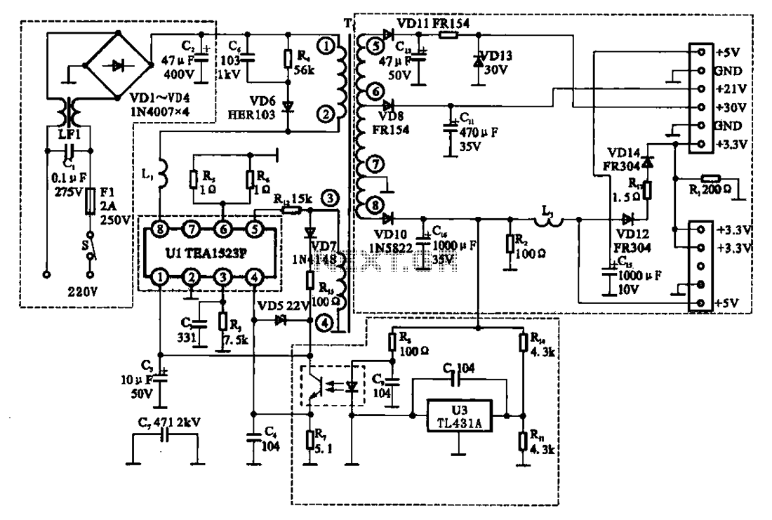
The East Shi IDS-2000F STB switching power supply circuit primarily consists of an AC input circuit, a switching oscillation circuit, an output circuit, and a secondary steady voltage control circuit. The AC input circuit includes a switch (S), fuse...

An electronic scale utilizes a pressure transducer (load cell) along with an analog-to-digital (A/D) converter to operate a digital display. The scale's range is determined by the specifications of the load cell, and the display is calibrated in suitable...
As with the Electronic sel. 8 we also have here a circuit with a choice of 8 different sources. The difference is that only two of the switches are used and the movement of commands is Up-Down in series....
The lack of compensation facilitates the processes of development and testing. The figure of 6 billion frequently appears as the estimated number of cell phones in use globally. Published estimates indicate an average. The discussion of compensation in electronic circuits...