
Electronic Touch Switch

The electronic touch switch serves as an effective alternative to mechanical contacts, addressing the issue of wear and tear associated with traditional mechanical switches. These touch switches operate by detecting the presence of a finger or conductive object near their surface, thus eliminating the need for physical movement of components. The primary advantage of this technology is its longevity, as there are no moving parts that can degrade over time.
In an electronic touch switch circuit, a capacitive or resistive sensing mechanism is typically employed. Capacitive touch switches work by measuring changes in capacitance when a finger approaches the sensor surface. This change triggers a microcontroller or a specialized IC to activate or deactivate the connected load, such as a light or motor. The circuit usually includes components such as a power supply, a sensing element (capacitive or resistive), a microcontroller for processing the input, and a relay or transistor for switching the load.
The design of an electronic touch switch circuit may also incorporate additional features such as adjustable sensitivity, debounce logic to prevent false triggering, and LED indicators to provide visual feedback. The use of a microcontroller allows for programming flexibility, enabling the implementation of various switching modes, such as momentary or latching actions.
Overall, electronic touch switches are advantageous in applications where reliability, durability, and user interface simplicity are critical. Their integration into consumer electronics, home automation systems, and industrial controls exemplifies their versatility and effectiveness in modern electronic design.Mechanical contacts have the disadvantage that they wear out. That is why it is practical to use an electronic ‘touch switch in some situations. With suc.. 🔗 External reference
Related Circuits
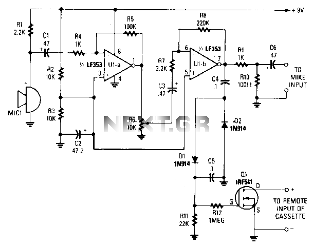
A sensitive electret microphone captures sound and transmits the signal to a two-stage amplifier circuit, comprising Ula and Ulb. The amplified output from Ulb is directed to a voltage-doubler circuit (consisting of D1, D2, C4, and C5). The output...
The ML4423 is an integrated controller designed for single-phase and two-phase AC induction motors. It features PWM (Pulse Width Modulation) capabilities for speed control and includes various protection circuits such as short circuit protection, fire protection, and a reference...
This circuit illustrates the LM2576T integrated circuit (IC) step-down switching power supply circuit diagram. Features include a 60V input voltage with output options of 3.3V, 5V, 12V, and 15V. The LM2576T is a popular voltage regulator known for its ability...
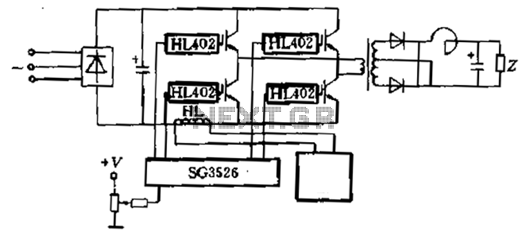
Applications are provided to complete the four-piece HL402 switching power supply system diagram, which drives four power IGBT switching power supplies. The IGBT drive pulse is generated by the SG3526. The HL component serves as a current sensor, utilized...
This circuit functions as a camera switch, allowing multiple cameras to be connected to a single monitor. It can operate in both manual and automatic modes. In automatic mode, the circuit utilizes a 555 astable multivibrator to generate a...
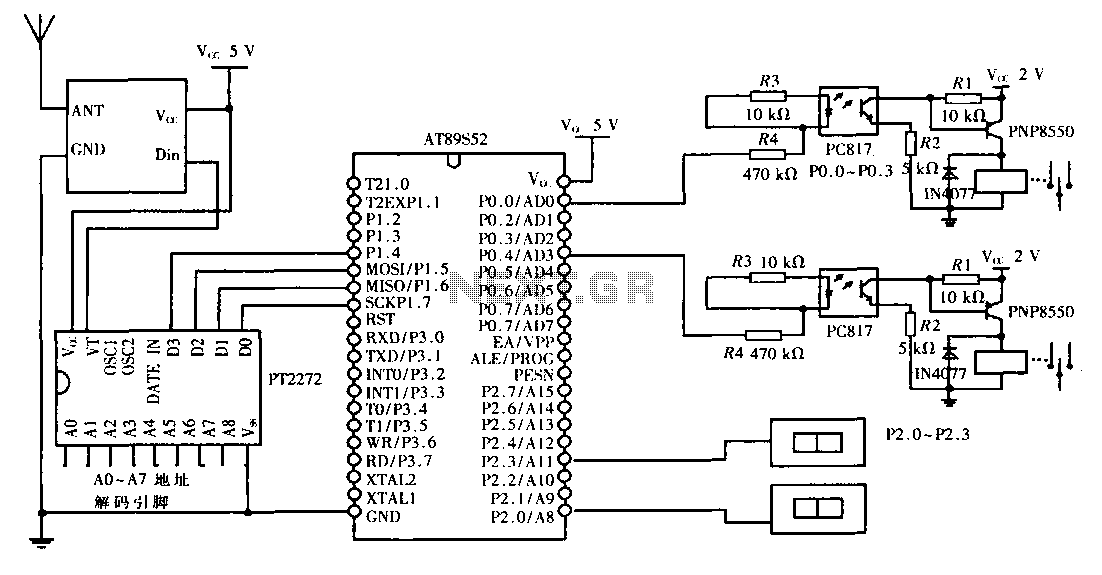
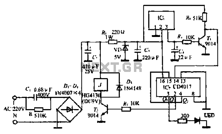
This design aims to create a long-distance wireless remote control switch lighting control system, which consists of a transmission system and a reception system. The system utilizes wireless transceiver modules for RF transmission and reception. The transmitting portion mainly...