
Electronic Touch Switch

The electronic touch switch described utilizes the LM393 comparator to effectively convert the resistance change due to skin contact into a digital signal. The circuit operates on the principle that the human body can act as a conductive path when a finger touches the contact plates. The design employs a voltage divider and a series of diodes to create a stable reference voltage, ensuring reliable operation. The output of the circuit is designed to toggle state based on the input from the touch contacts, allowing for a responsive switching mechanism that can be integrated into various applications.
The choice of components is critical for ensuring the touch switch's functionality. The LM393, known for its low power consumption and dual comparator design, is suitable for battery-operated applications. The resistors R1, R2, R3, R4, and R5 are selected to provide the necessary voltage thresholds for the comparators to operate correctly. The inclusion of capacitors, such as C1, helps filter out noise and prevents false triggering from ambient electrical interference, which is particularly important in environments with AC mains power.
For practical applications, the touch switch can be housed in an enclosure that minimizes exposure to environmental factors while allowing for effective touch input. The mounting of the metal plates should be done carefully to ensure they are close enough for effective sensing but not so close that they create a short circuit. The overall design emphasizes reliability, ease of use, and safety, making it suitable for a range of applications where mechanical switches may fail due to wear.Mechanical contacts have the disadvantage that they wear out. That is why it is practical to use an electronic touch switch` in some situations. With such a touch switch the resistance of the human skin is used for the switching action. The schematic shows the design of a circuit that senses the resistance of the skin and converts it into a useful switching signal. The touch switch contacts can be made from two small metal plates, rivets, nails, etcetera, which are placed close together on a non-conducting surface. In this circuit a comparator of the type LM393 has been used. In the idle state there is, via R1, a voltage equal to the power supply voltage on the non-inverting input of IC1a.
Because the inverting input of IC1a is set with R2 and D3 to D5 at the supply voltage minus 1. 8 V, the open-collector output of IC1. a is, via R3, equal to the power supply voltage. This voltage is inverted by IC1. b. The voltage at the non-inverting input of IC1. b amounts to half the power supply voltage (through voltage divider R4 and R5) and is lower than the voltage on the inverting input. The output of IC1. b is therefore a 0`. If the two touch contacts are bridged with a finger, the voltage at the non-inverting input will become low enough to cause the comparator to toggle state.
The moistness of the skin results in a resistance of 1 to 10 MR. If this circuit is used in the vicinity of equipment that`s connected to the mains, then it can be sufficient to touch only the upper contact to operate the switch, provided that the circuit has been earthed. The body then acts as an antenna which receives the 50 Hz (or 60 Hz) from the mains. This is enough to toggle IC1. a at the same 50 Hz. C1/R3 prevent this 50 Hz from reaching the input of IC1b and provide a useable pulse` of about 10 s at the output of IC1.
b. Note that a fly walking across the touch switch conducts enough to generate a switching signal. So do not operate important things with this circuit (such as the heating system or the garage door). Do not make the wires between the touch contacts and the circuit too long to prevent picking up interference.
The power supply voltage for the circuit is not very critical. Any regulated DC voltage in the range from 6 to 20 V can be used. 🔗 External reference
Related Circuits
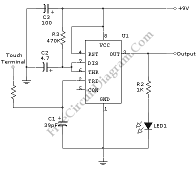
A schematic diagram of a touch switch circuit is presented. This circuit comprises a timer, a one-shot multivibrator, and a touch terminal. The timer utilized in this circuit is a 555 timer, which is connected to the one-shot multivibrator....
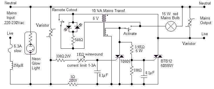
Full short-circuit and overcurrent protection is given by this circuit suitable for workbench applications in technical schools and laboratories where there is a need to work directly with the mains. Additional features are a clearly visible red lamp indicating...
The capability to control lights and fans wirelessly has transitioned from an expensive luxury to widely accessible consumer solutions. Nevertheless, creating a custom solution remains an engaging project for hobbyists and tinkerers. RobotGrrl has developed user-friendly libraries aimed at...
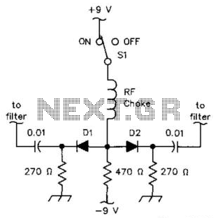
D1 and D2 can be IN914B or HP2800-series diodes (for UHF). The loss is over 60 dB in the off state and less than 3 dB at 3.5 to 30 MHz (using common IN914B diodes). The circuit utilizes D1 and...

The TEA5551T monolithic integrated radio circuit can be utilized to design an AM radio receiver circuit intended for portable use with headphones. This circuit incorporates all necessary components for a complete AM radio receiver, including a fully integrated AM...
Speaker relay delay controlling circuit for audio amplifier The speaker relay delay controlling circuit is designed to manage the connection between an audio amplifier and the connected speakers, ensuring that the speakers are activated only after a predetermined delay. This...