
Touch Switch Monostable/Timer with 555 IC

The touch switch circuit operates by utilizing the 555 timer in monostable mode, where the timer generates a single pulse when triggered by the touch terminal. The touch terminal acts as a momentary switch that, when activated, sends a signal to the timer, initiating the timing sequence. The one-shot multivibrator, connected to the 555 timer, ensures that a single output pulse is generated for a predetermined duration, defined by the resistor (R3) and capacitor (C2) values.
The output of the circuit can be interfaced with various components such as power transistors, CMOS circuitry, hexFET transistors, or optocouplers, allowing for a wide range of applications, including LED control, relay activation, or other electronic device management. The selection of the output stage component depends on the required load current and voltage specifications.
The timing characteristics of the circuit are governed by the formula: T = 1.1 * R3 * C2, where T is the time duration for which the output remains high. By adjusting the resistance of R3 or the capacitance of C2, the ON time can be finely tuned to meet specific application requirements. Increasing either component will result in a longer ON time, providing flexibility in the design and functionality of the touch switch circuit. Conversely, reducing the values will decrease the ON time, allowing for quicker response times in applications where rapid switching is desirable.
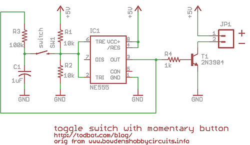
Overall, this touch switch circuit exemplifies a versatile and efficient method for controlling electronic devices through a simple touch interface, leveraging the reliable performance of the 555 timer and the configurability of passive components.A schematic diagram of a touch switch circuit is shown below. This circuit consist of timer, one shoot multivibrator and touch terminal. As timer, this circuit uses 555 timer which is connected to one-shot multivibrator. The touch terminal is used to trigger this circuit. The output of this circuit can be used to drive a power transistor, CMOS ci rcuitry, hexFET transistor or optocoupler. Here is the schematic diagram of the touch switch circuit: Using the given values as shown in the schematic diagram, this circuit has timed ON period of 4 seconds. The value of C2 and R3 determines the ON time, increasing the value of C2 or R3 will increase the ON time.
The ON time is decreased if the value of C2 or R3 is decreased. 🔗 External reference
Related Circuits
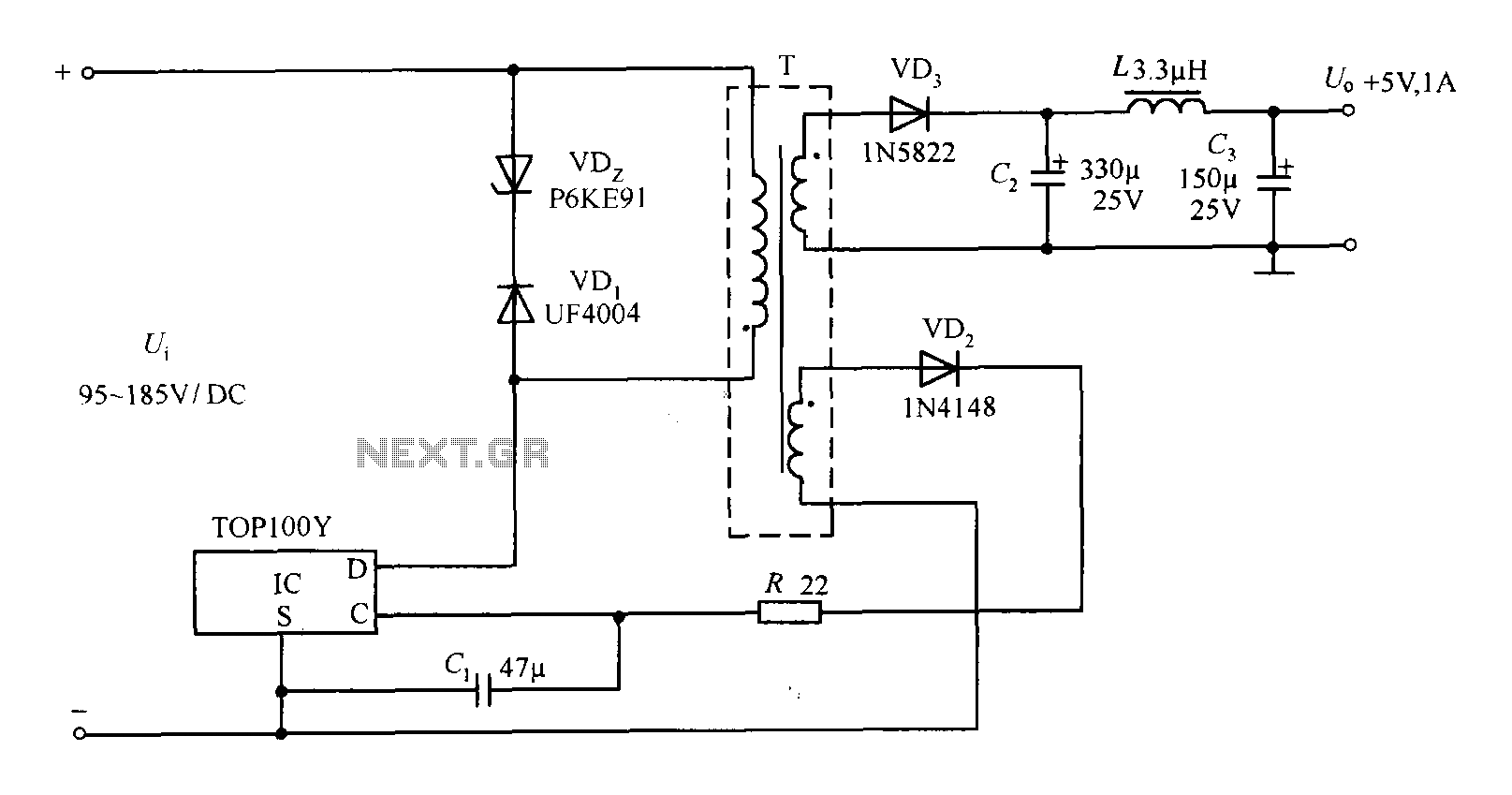
The TOP100Y is a flyback DC switching power supply circuit with a +5V, 1A output. This power supply features a feedback circuit that directly regulates the output voltage, making it suitable for applications that require electrical isolation and minimal...

The circuit utilizes a 555 timer IC to create a lighting group delay effect, as illustrated in Figure 2-46. It consists of the 555 IC along with a resistor and capacitor configuration that establishes the delay. The circuit remains...
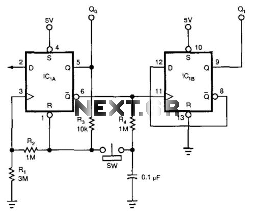
This circuit utilizes a 74HC74 flip-flop, although any CMOS variant of this component can be employed. IC1A functions as a true/complement buffer. Resistors R1 and R2 ensure that IC1A exits the reset state prior to the clock edge occurrence....
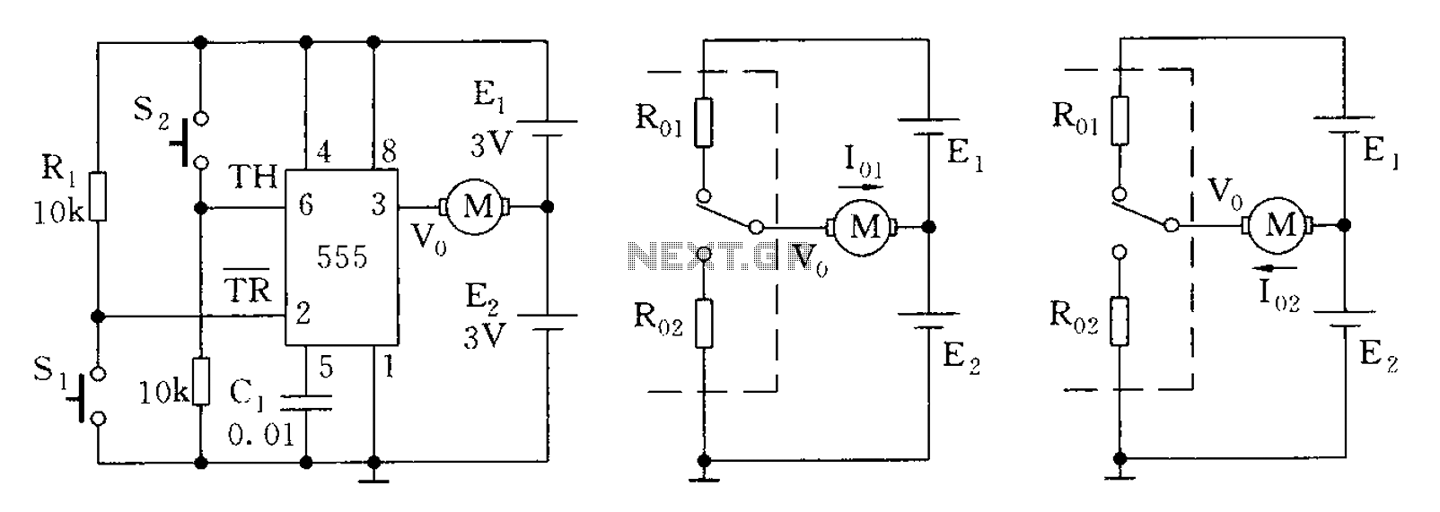
The 555 timer in bistable mode has fewer applications compared to its stable and monostable modes. Bistable mode refers to the circuit configuration based on the R-S (Reset-Set) trigger mode. An example of this is a micro-motor reversing control...
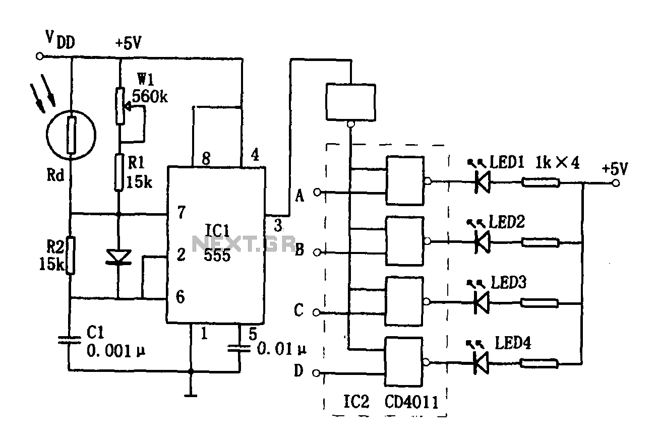
The brightness display circuit consists of a light-sensitive sensor, an oscillation circuit, and an LED display circuit. The light-sensitive sensor is a photosensitive resistor (Rd). The multivibrator is composed of Rd, R1, W1, R2, and C1, along with a...
Most circuits operate based on a flip-flop principle. Instead of using a dedicated flip-flop chip, a 555 timer chip can be utilized, as it contains a single flip-flop and several comparators. After researching various resources, including Forrest Mims' electronics...