
Electronic Transformers Modulation

The pi-filter technique is a sophisticated application of wave-filter principles that enhances the performance of modulation transformers in high-level amplitude-modulated radio transmitters. The design intricacies involve careful consideration of component sizing to achieve optimal impedance matching and efficiency. The use of a class B amplifier as the modulator plays a critical role in maintaining audio fidelity while minimizing the physical size of the components.
The pi-section high-pass filter configuration, which integrates the output transformer, coupling capacitor, and modulation reactor, is engineered to provide a characteristic impedance that aligns with the power amplifier's plate input resistance. This alignment is crucial for maximizing power transfer and ensuring that the modulated signal maintains integrity across a range of frequencies.
The advantages of the pi-filter method are particularly pronounced in its ability to maintain a high power factor across a broad frequency spectrum, thereby improving the overall efficiency of the system. The reduction in reactive components allows for a more compact design without sacrificing performance, which is essential in modern radio transmitter applications where space and efficiency are paramount.
Furthermore, the pi-filter's ability to limit surge voltages across the coupling capacitor enhances reliability and longevity, as the components are less likely to experience breakdown under normal operating conditions. This reliability is further supported by the inherent characteristics of class B amplifier tubes, which adapt to varying load conditions, thus ensuring consistent voltage delivery even as the load impedance changes.
In conclusion, the pi-filter method represents a significant advancement in modulation transformer design, offering improved audio quality, reduced component size, and enhanced operational efficiency, thereby setting a new standard for high-level amplitude-modulated radio transmitters.Wave-filter principles are applied in many circuits other than filters. An example is the design of modulation transformers for high-level amplitude-modulated radio transmitters. Some of these transformers are large. In plate-modulated power amplifiers, the modulator power required to produce 100 per cent modulation is half of the power amplifier
input. Improved audio quality and reduction in size of components are achieved through the use of what may be called the pi-filter method. For low modulation frequencies, this method may be illustrated by means of the circuit diagram of Fig.
145(a). The modulator usually is a class B amplifier. Output transformer OCL, coupling capacitor, and modulation reactor combine to form a pi-section high-pass filter, Fig. 145(b). The elements are proportioned for characteristic impedance equal to the equivalent plate input resistance EB/IB of the modulated power amplifier.
Formerly these components were made as large as was considered practical. Transformer secondary and reactor reactances were each 3 to 4 times the power amplifier plate input resistance, and the coupling capacitor reactance was a fraction of this resistance, at the lowest modulation frequency. Advantages of the pi-filter are a reduction of the two inductive reactances to 1. 41 times the terminating load resistance, and increase in capacitive reactance to the same value, at a low frequency f1, which is 1.
41 times cut-off frequency of the filter. Down to f1 the filter maintains a tube load of almost 100 per cent power factor, although the ohmic value rises to 190 per cent of the terminating load resistance at f1. The voltage required for constant output rises to 138 per cent of normal. Partly compensating for this defect is the tendency of class B amplifier tubes to deliver higher voltages with higher tube load impedances.
Thus, in a certain radio transmitter, the type 805 modulator tubes deliver 1, 035 peak volts per side into a normal tube load of 1, 860 ohms. At 30 cycles, the lowest audio frequency, the load impedance rises to 3, 600 ohms, and the voltage required for full output is 1, 440 volts.
Plotting a 3, 600-ohm load line on the tube curves shows that 1, 275 volts will be delivered at 30 cycles, which is 1 db down from normal. To obtain the same frequency response with the older "brute force" method, at least twice the values of transformer and reactor inductance and much more coupling capacitance would have been necessary.
The voltage across the capacitor increases as the capacitance decreases, but surge voltages often exist across the coupling capacitor in service. The voltage rating was formerly determined more by these surges than by normal voltage. With the pi-filter method, the normal voltage at low frequencies cannot be greatly exceeded in service, owing to the limitation in voltage output of the tubes.
Hence, the reduction in coupling capacitance is a real one and is offset very little by increases in voltage rating. These points are made clearer by reference to Fig. 146. Phase shift between transformer and load voltages is 90 ° at f1. At cut-off (= 70 per cent of f1) the tube voltage for constant output is 224 per cent of the load voltage.
A tube would not deliver so much voltage with this type of load, especially when the power factor is so low. The corresponding capacitor voltage at cut-off frequency is 284 per cent of ER; it would not be delivered either, for the same reason.
The useful frequency range is higher than f1. Another advantage of the pi-filter over the older method is the high power factor load down to frequency f1. The maximum tube load phase angle above f1 is 8 °, and at frequencies above 3f1 the phase angle is zero.
At 3f1 the tube load impedance is equal to R. Hence the tube works into a unity power-factor load of constant value at frequencies above 3f1. For the same size of inductive components, the "brute force" system would h 🔗 External reference
Related Circuits
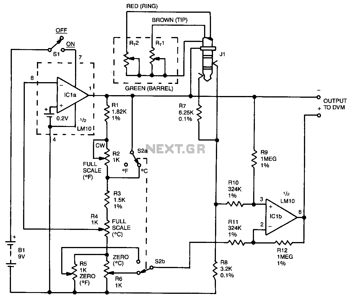
This oscillator circuit features a quartz crystal with a nominal resonant frequency of 262,144 Hz, which is cut in an orientation that provides a significant linear coefficient of frequency variation with temperature. In this configuration, the oscillation frequency is...
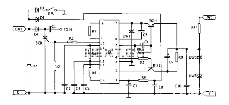
An AC magneto is connected to an external circuit. The output is rectified by diode D1 and stored in capacitor C1. Additional rectification is performed by diodes D4, along with resistors R9 and capacitors C7 and C8, which filter...
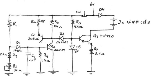
Designing a true constant-current AA NiMH charger requires selecting an appropriate power supply. The voltage must be high enough to prevent the constant current (CC) transistor from saturating, yet low enough to minimize power dissipation in the transistor. The...
Why an electronic cricket? Many people enjoy the sound of crickets, especially those living in urban areas. This electronic cricket circuit operates in pulses, creating a similar sound. The electronic cricket circuit is designed to replicate the natural sound of...
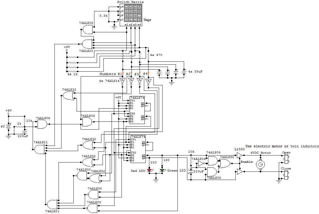
This circuit is an electronic locker controlled by a combination of switches (a code). It features a switch matrix located on the locker door, consisting of a unit of switches arranged in four rows and four columns, totaling eight...
The sphygmomanometer can be categorized into two main types: the mercury sphygmomanometer and the electronic sphygmomanometer. The mercury sphygmomanometer is known for its accuracy, but it requires professional operation and is prone to observational errors due to subjectivity. Additionally,...