
On-off controller

This AC line-operated on/off controller circuit utilizes a triac as the main switching element, allowing for efficient control of AC loads. The circuit's operation begins when power is supplied, initiating the timing sequence. The timing is managed by two diodes that establish the intervals of 8 hours and 20 hours. The first interval (8 hours) is defined by the charging and discharging of a timing capacitor, which is controlled through a resistor network to set the desired time period.
During the first time interval, the output load is energized, allowing current to flow through the triac. A transistor acts as a buffer for the TIM1 output, ensuring that sufficient gate current is supplied to the triac, facilitating its conduction. The triac remains in the 'on' state for the duration of the 8-hour period.
Once the 8 hours elapse, the circuit transitions to the second time interval, where the output load is turned off for 20 hours. This is accomplished by discharging the timing capacitor, which results in the transistor ceasing to provide gate current to the triac, thereby interrupting the current flow to the load. The cycle then repeats, providing a reliable on/off control for the load with minimal mechanical wear, as there are no moving parts involved.
This design is particularly advantageous for applications requiring timed control of electrical devices, such as lighting systems or industrial equipment, where prolonged operation and energy savings are essential. The solid-state nature of the circuit enhances durability and reduces maintenance needs compared to traditional mechanical switches.The ac line-operated on/off controller is a simple, reliable solid-state alternative to a motive driven cam switch. Time 1 and time 2 are programmed by diodes to be 8 hours and 20 hours respectively. The TIM1 output is buffered by a transistor to supply gate current to a triac which switches the output load
When power is applied to the circuit, the output load is switched on for 8 hours then off for 20 hours repeatedly.
Related Circuits
This project involves an automatic room light controller with a visitor counter utilizing a microcontroller. It is a dependable circuit designed to manage room lighting while accurately counting the number of individuals present. When a person enters the room,...
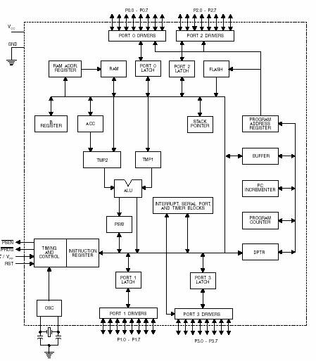
A microcontroller (MCU) is a compact computer integrated into a single circuit, comprising a relatively simple CPU along with supporting functions such as crystal oscillators, timers, sensors, and serial and analog input/output (I/O). Microcontrollers are designed for small-scale applications,...
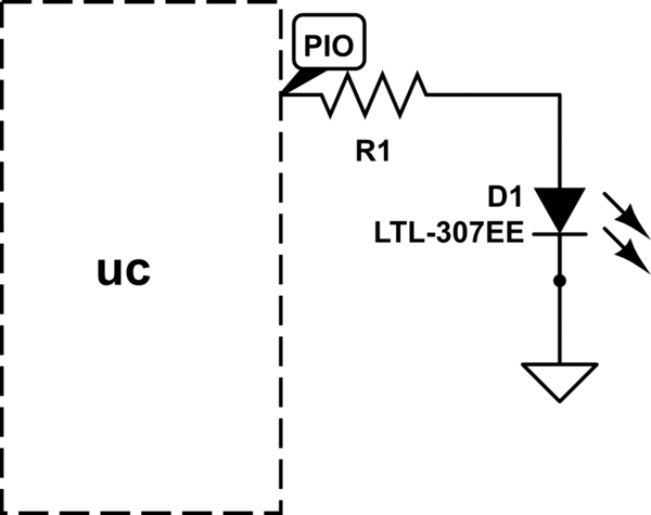
The LED will illuminate when the PIO (Programmable Input/Output) pin goes low, functioning similarly to a ground connection. In this configuration, the current is sourced from the power supply rather than the PIO, as in the first method. It...
The L29 Stepper Motor Controller IC facilitates the control of four drive signals for two bipolar and four unipolar footfall motors in a microcomputer-controlled appliance. It allows for motor operation in half-step, full-step, and wave drive modes, utilizing switch-mode...
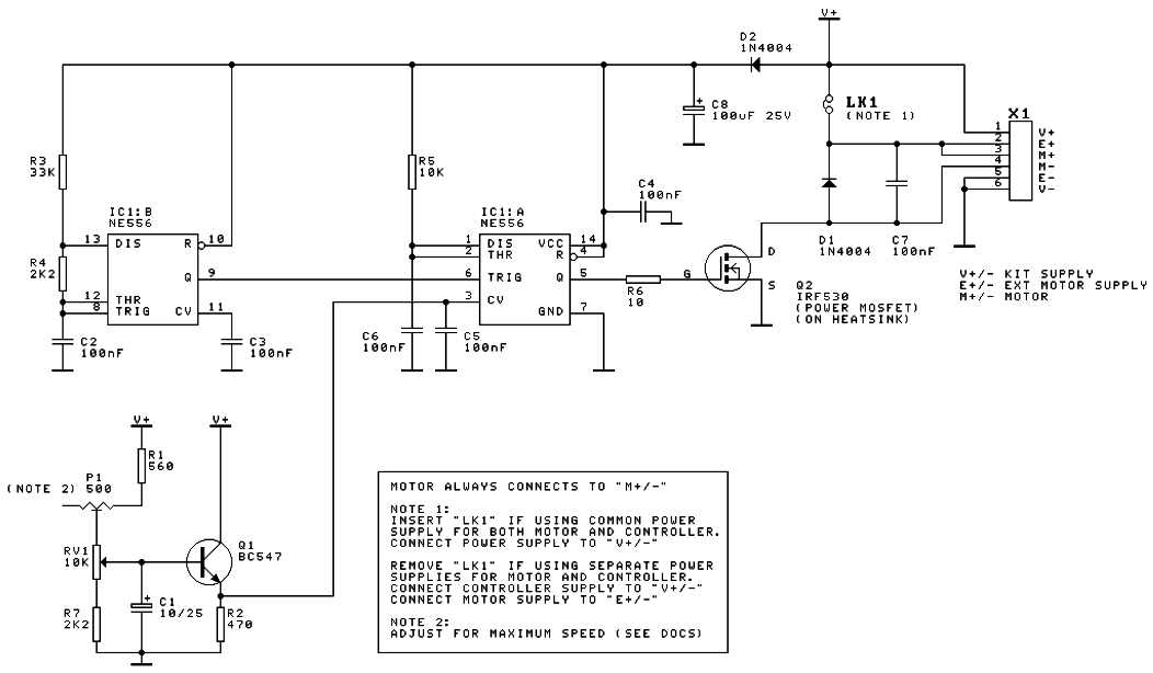
A DC motor speed controller circuit utilizes two timers configured as a Pulse Width Modulator (PWM). The integrated circuit employed for this purpose is the NE556, which is a dual timer/oscillator using NMOS technology. The DC motor speed controller circuit...
DC motor interfacing with a microcontroller using the L293D H-bridge and a transistor-based H-bridge. DC motor speed control is achieved through PWM. The DC motor is interfaced with 8051, AVR, and PIC microcontrollers. The circuit design for interfacing a DC...