
Electronic Watchdog

The electronic watchdog circuit is designed to enhance security by simulating the presence of a dog. It typically consists of several key components, including a motion sensor, a sound module, a microcontroller, and a power supply.
The motion sensor, often an infrared (IR) or ultrasonic type, detects movement within the specified 10-meter radius. Upon detecting motion, it sends a signal to the microcontroller, which processes the input and activates the sound module. The sound module is programmed to produce a barking sound that mimics a real dog, enhancing the deterrent effect.
The microcontroller plays a crucial role in managing the operation of the circuit. It is programmed to initiate the barking sequence for a duration of 10 seconds. If the motion sensor continues to detect movement after this time, the microcontroller can be configured to either repeat the barking sound or enter a standby mode, effectively reducing power consumption when no further activity is detected.
Power supply options for the circuit may include batteries or a direct connection to an AC source, depending on the intended application and installation location. The circuit can be housed in a weatherproof enclosure for outdoor use, ensuring durability and reliability in various environmental conditions.
Overall, the electronic watchdog circuit combines advanced sensing technology with realistic sound output to create an effective security solution that can help deter unauthorized entry into a premises. As shown for the electronic watchdog circuit. It has the ability of ordinary dog guard the house. Whenever someone enters the door 10 meters monitored area, it will send out a realistic barking. Such calls can be maintained for 10 seconds, if the person does not leave, the electronic watchdog would have been called down.
Related Circuits
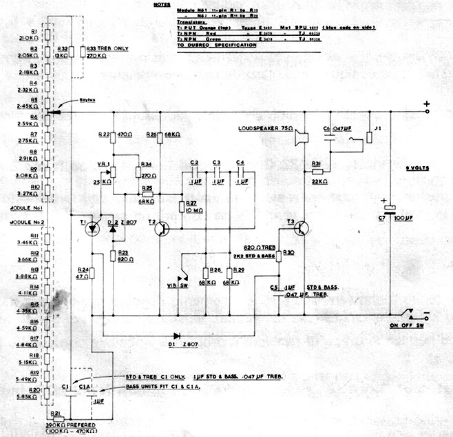
A recently discovered schematic appears to be authentic and does not include the 555 timer. Additionally, a picture of Brian Davis on this page shows him holding the etch mask, which does not exhibit any features resembling a socket...
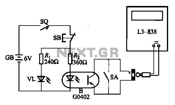
An electronic calculator features an automatic counting interface circuit, as illustrated in the accompanying figures. Figure (a) depicts a stroke switch controlled via optocoupler B. Figure (b) shows the application of a reed switch (KR) for pulse control signals....

To generate and maintain the endocochlear potential (EP), perilymphatic potassium ions (K+) enter fibrocytes (F) through the Na+/K+-ATPase and Na-K-Cl cotransporter. Gap junction networks connect fibrocytes to strial basal (SB) and intermediate (SI) cells, allowing ions to enter the...

This metal detector circuit project is a simple design based on common electronic components. It utilizes transistors to provide a visual indication through an LED and an acoustic signal to alert users when metal is detected. To calibrate the...
The sound produced mimics the rise and fall of an American police siren. When first powered on, the 10µF capacitor is discharged, and both transistors remain off. Upon pressing the push button switch, the 10µF capacitor begins to charge...

This circuit generates a ringing sound similar to that produced by modern telephones. It comprises three nearly identical oscillators connected in a series configuration, each generating a square wave signal. The frequency of each oscillator is determined by the...