
Electronically Designed Dice Game Circuit by LM555

The electronic dice circuit utilizes a 555 timer configured in astable mode to generate a series of pulses that simulate the rolling of a dice. The frequency of these pulses can be adjusted to control the speed of the dice roll. The circuit typically includes a few key components: resistors, capacitors, and possibly a display mechanism such as LEDs or a seven-segment display to represent the dice values.
In this configuration, the timing components—resistors (R1, R2) and a capacitor (C1)—determine the frequency of oscillation. The output from the 555 timer is a square wave signal that can be used to trigger the display. When the circuit is powered, the 555 timer continuously switches its output between high and low states, creating a rapid sequence of flashes on the display.
To represent the values of a dice (1 through 6), a decoding mechanism is often employed. This can be achieved using a binary decoder or a simple microcontroller that interprets the output from the 555 timer. The output can be mapped to the corresponding numbers displayed, ensuring that only one value is shown at a time.
The circuit may also include a reset button to stop the rolling effect and latch the current value displayed. This feature allows users to "roll" the dice by pressing a button, which starts the oscillation, and then pressing the reset button to freeze the display at a random value.
Power supply considerations are important; the circuit can typically operate on a standard voltage, such as 5V or 9V, depending on the specifications of the 555 timer and the display components used. Proper decoupling capacitors should be included to filter noise and ensure stable operation.
Overall, this electronic dice circuit is a practical application of the 555 timer in astable mode, demonstrating its versatility in generating random outputs suitable for gaming applications.The objective of the circuit is to build an electronic dice based on the functions of a 555 timer integrated circuit that operates in the astable mode. LM.. 🔗 External reference
Related Circuits
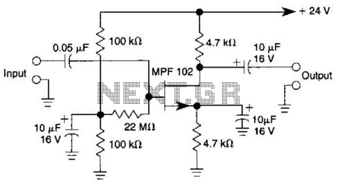
In this amplifier circuit, the gate of the MPF 102 is biased with an external voltage. This circuit achieves tighter control of the operating point and biasing conditions. The amplifier circuit utilizing the MPF 102 field-effect transistor (FET) is designed...
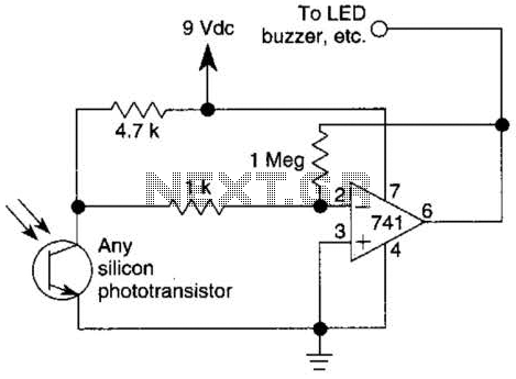
This circuit represents one of the simplest infrared (IR) receivers that can be constructed. The components are inexpensive, the layout is not critical, and a 9-V battery provides a long operational life. The described IR receiver circuit typically consists of...
This circuit is not highly critical and can utilize various devices (such as a tape player with a message recorded on an endless tape) that do not overload the circuit or the telephone line. The incoming line is safeguarded...
This page features H-Bridge circuits used for controlling direct current motors. Several designs are shown using both CMOS and Bi-Polar power devices. These circuits could be used as the basis for Model Railroad DCC Boosters or PWM motor controllers....
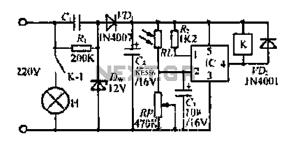
At dawn, light illuminates the photosensitive resistor RL, causing its resistance to decrease. This switch IC (2) exhibits a high electrical footprint. When light is present, the relay K does not activate. At night, in the absence of light,...
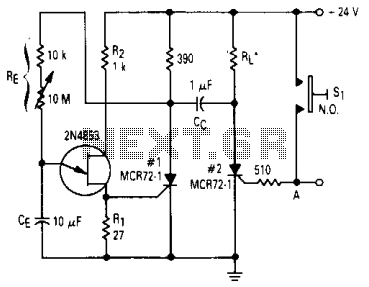
After one cycle of operation, SCR1 will be activated, resulting in a low voltage being applied to the UJT emitter circuit, which interrupts the tuning function. When pushbutton SI is pressed, or a positive pulse is applied at point...