
A long light power control circuit

The circuit described utilizes a photosensitive resistor (commonly known as a light-dependent resistor, or LDR) to control the operation of a lamp based on ambient light conditions. During daylight hours, the LDR's resistance decreases significantly, preventing the associated switch IC from activating the relay. This results in the lamp remaining off, conserving energy during times when it is not needed.
In contrast, at night or in low-light conditions, the resistance of the LDR increases, which causes the voltage at pin 2 of the switch IC to drop to a low level. This change in voltage level triggers the IC to enter a conductive state. Consequently, the relay K is activated, closing its normally open contacts (K-1). This action completes the circuit to the lamp, allowing it to turn on and provide illumination.
The switch IC is designed to handle the electrical characteristics of the circuit, ensuring reliable operation while minimizing power consumption. The relay serves as an interface between the low-power control signal from the IC and the higher power requirements of the lamp, allowing for safe operation without direct electrical connection between the two.
In summary, this circuit effectively automates lighting control based on environmental light levels, enhancing convenience and energy efficiency. The integration of the photosensitive resistor with the switch IC and relay provides a straightforward yet effective solution for automatic lighting applications. At dawn, the light is irradiated onto the photosensitive resistor RL, it reduces resistance This switch ICs (2) exhibits high electrical foot. I. lC end, the relay K does not s uck desk, lamp does not light. To r night, dark, darken, the photosensitive resistor RL was high resistance, so lC VJ (2 pin level goes low .IC conduction, the relay K assault units, which normally open contacts K-l cut Taiwan, lamps bright.
Related Circuits
This light sensor switch circuit enables the automatic activation of a lamp when ambient light levels decrease, such as during nightfall. The duration for which the lamp remains on can be adjusted using potentiometer P1, with a range of...
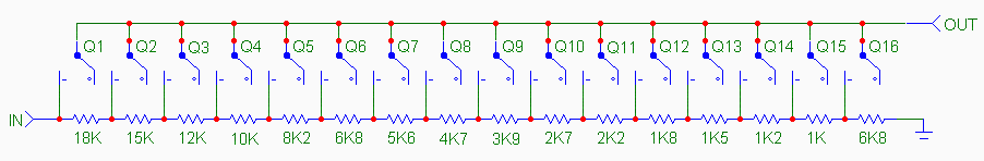
The traditional potentiometer is implemented with an electrical contact that slides over a resistive layer. An example of a well-known audio-grade potmeter is the Alps Blue. A high-end (good and costly) alternative is the rotary switch. This device consists...
The following circuit illustrates the use of a 555 integrated circuit (IC) for an infrared (IR) remote control extender circuit. Features include support for 850 nm and 950 nm signal wavelengths, along with the capability to generate control pulses. The...
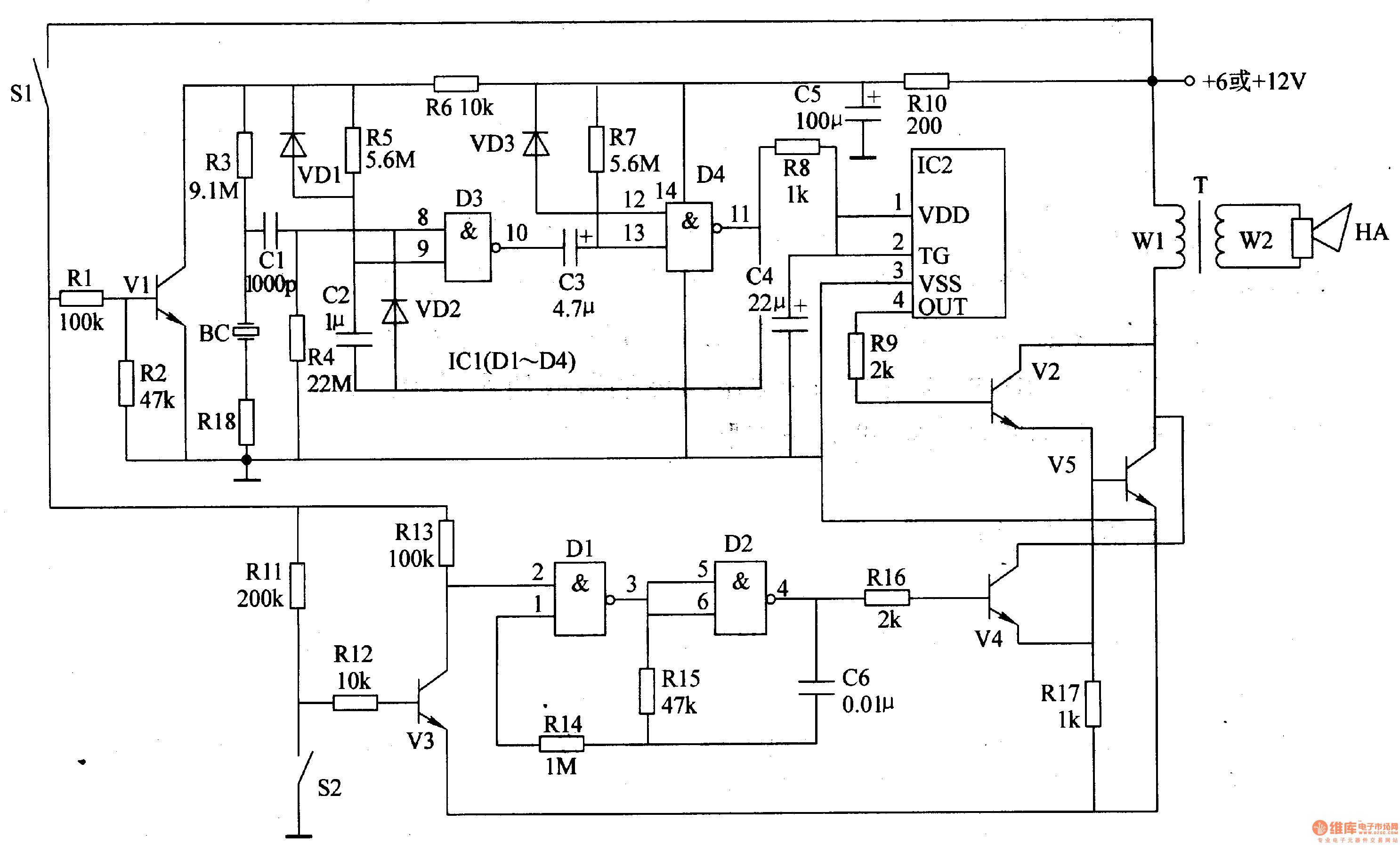
The motorcycle anti-theft alarm circuit consists of several components, including the anti-theft detection circuit, the control circuit, the sound generator, the audio oscillator, and the power amplifier output circuit, as illustrated in figure 7-91. The anti-theft detection circuit is...
That circuit is based at a technique to remove or neutralize the salt in water, and protect the pipes at home as well as the washing machines or our selves from salt. Its called water softener and its automated...
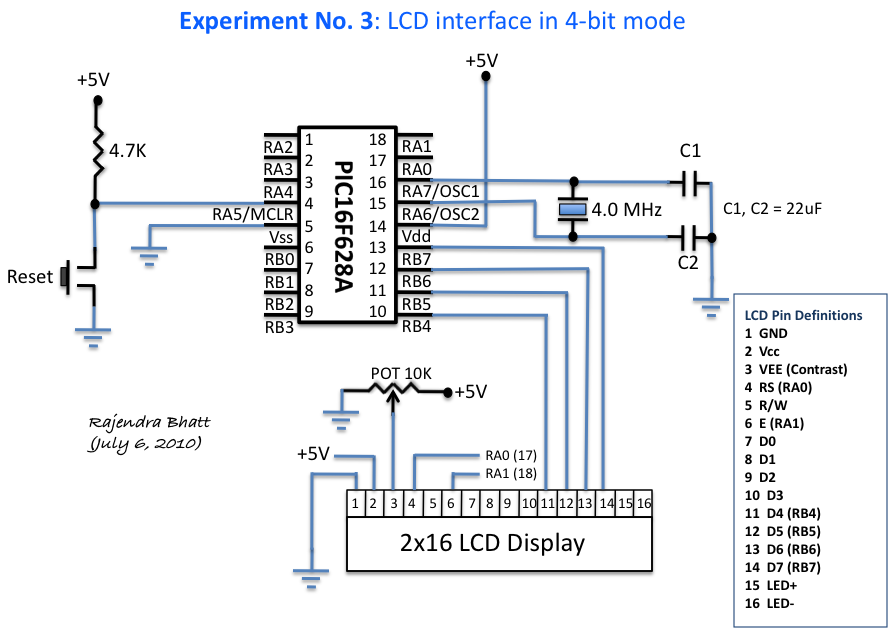
An HD44780 Character LCD is a liquid crystal display (LCD) device designed for interfacing with embedded systems. These screens are available in various configurations, including 8x1 (one row of eight characters), 16x2, and 20x4. The most commonly produced configuration...