
transistors LC circuit
The described LC oscillator circuit operates based on the principles of resonance and feedback. An LC circuit consists of an inductor (L) and a capacitor (C) that are connected together, forming a resonant tank circuit. At resonance, the circuit will oscillate at its natural frequency, determined by the values of L and C. The output frequency (f) can be calculated using the formula:
f = 1 / (2π√(LC))
In this specific case, the expected frequency is around 212 Hz, which can be verified by rearranging the formula to find the required inductance or capacitance values if one is known.
The transistor in the circuit serves as an active component that compensates for energy losses inherent in real components. When the circuit oscillates, the energy stored in the inductor and capacitor dissipates due to resistive losses. The transistor, controlled by the feedback from coil L2, acts as a switch that periodically injects energy back into the circuit, sustaining the oscillation.
To ensure proper operation, it is crucial to select a transistor that can handle the required current and voltage ratings. Factors to consider include the transistor's gain (β), frequency response, and switching speed. The gain of the transistor should be sufficient to amplify the signal from the coupled coil L2. Additionally, the maximum collector current and collector-emitter voltage ratings must exceed the circuit's operational requirements to prevent damage.
When troubleshooting simulation discrepancies, it is advisable to check the following:
1. Component Values: Ensure that the inductor and capacitor values used in the simulation match those in the physical circuit.
2. Parasitic Elements: Real-world components possess parasitic capacitance and inductance that can affect performance. These should be included in simulation models.
3. Transistor Parameters: Verify that the transistor model used in the simulation accurately reflects the characteristics of the physical component.
4. Power Supply: Ensure that the power supply voltage is stable and within the operational range of the transistor.
By addressing these factors, it becomes possible to improve the simulation results and ensure that the LC oscillator functions as intended in practical applications.Build the LC oscillator show on the bottom of this page for some school project and I`m having a bit of problems translating the theoretical circuit into a real-world one. I think I get how the circuit works on paper. We have a LC resonant circuit which will produce a certain output frequency. Because the energy in the circuit gets t ransferred out due to differences between theoretical components and real world components, the transistor is there to keep adding the energy into the circuit. The transistor is controlled by the coupled coil L2 in which we get current induced by the coil L which keeps switching the transistor In some simulations I used that transformer and a $ 470 mu F$ capacitor (I just happen to have one in my drawer) and the expected frequency should be around 212 Hz.
Here`s my question: How do I figure out why this doesn`t simulate well and how do I determine what I need to look for when picking a transistor for the circuit 🔗 External reference
Related Circuits
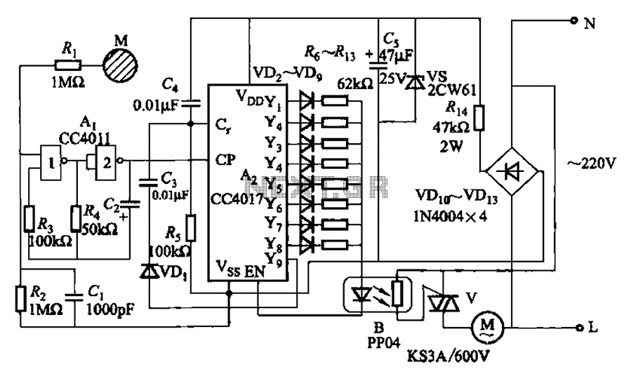
The circuit depicted in Figure 3-7 utilizes a touch sensor chip in conjunction with a conductive sheet. It is designed to achieve eight different speed settings. The CC4011 timing pulse oscillator is comprised of an integrated circuit. The configuration...
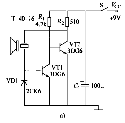
The ultrasonic transmitter circuit T-40-16, along with various discrete components, functions as a feedback sensor. The transistors VT1 and VT2 create a robust positive feedback oscillator that converts an electric signal into an ultrasonic oscillation signal, with the oscillation...
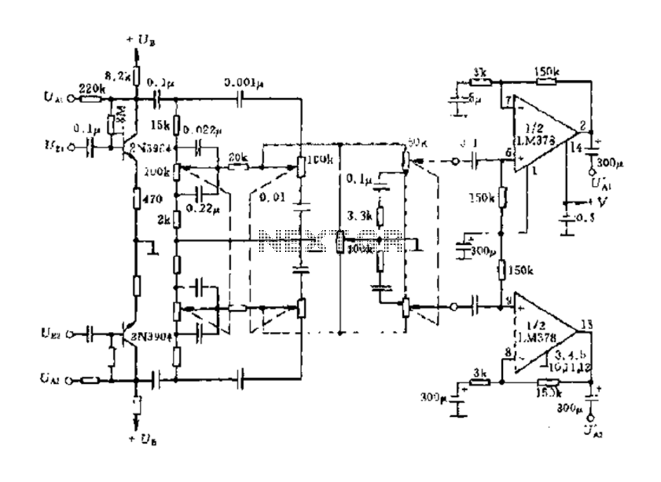
The dual-channel circuit features the LM378 dual operational amplifier and operates with a supply voltage of 24V, supporting an 8-ohm load (or 16 ohms). Each channel delivers an output power of 4W. The circuit includes internal current limiting and...
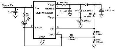
The ADM666A application note provides a detailed explanation of a low-cost battery charger circuit, including maximum output voltage, charge termination voltage calculation, battery voltage level monitoring, and circuit efficiency optimization. The ADM666A utilizes an NPN transistor and a P-channel...
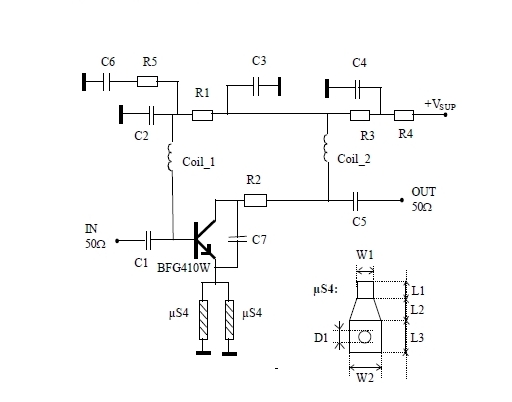
This 900 MHz amplifier circuit is constructed using the BFG480W transistor, which exhibits excellent linearity performance. As a result, the BFG480W is highly suitable for low-noise amplifiers (LNAs) that require high linearity. The 900 MHz amplifier circuit utilizing the BFG480W...
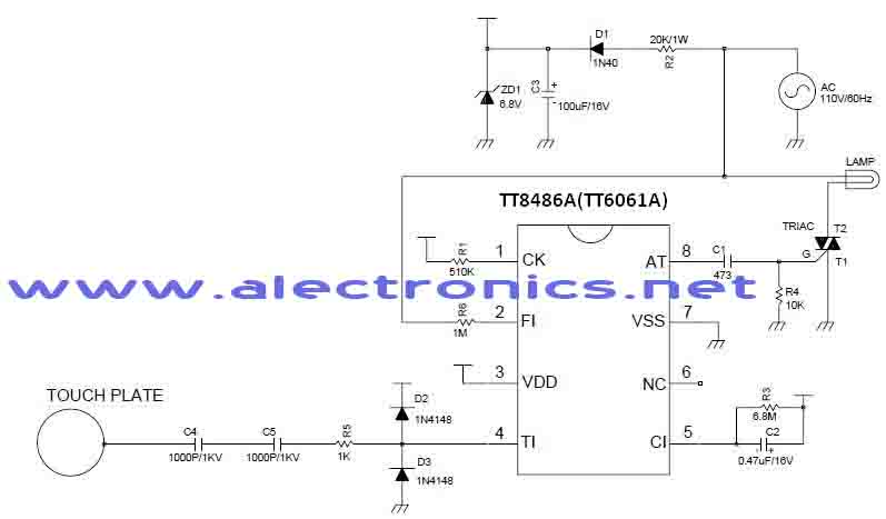
A simple dimmer circuit can be constructed using the CMOS ICs TT8486A and TT6061A, allowing control over the intensity of an incandescent lamp through a touch contact. This electronic touch dimmer can increase the brightness of incandescent lamps in...