
Eliminate hum instrumentation amplifier INA101 circuit

The instrument amplifier circuit is designed to effectively eliminate hum and noise from audio signals, enhancing the overall signal quality. The INA101 operational amplifier is chosen for stages A1 and A2 due to its high common-mode rejection ratio (CMRR) and low noise characteristics, which are essential for precision measurement applications. The INA105 in stage A3 serves a similar role, providing additional amplification while maintaining the integrity of the signal.
The feedback circuit plays a crucial role in stabilizing the amplifier's gain and reducing unwanted interference. By carefully selecting resistors and capacitors within the feedback loop, the circuit can be tuned to target specific frequencies of hum, commonly arising from AC power sources. This targeted approach allows for effective suppression of noise without significantly affecting the desired signal.
In designing the circuit, attention must be given to the layout to minimize inductive and capacitive coupling, which can introduce additional noise. Proper grounding techniques and the use of twisted pair wiring for signal paths can further enhance performance. Additionally, bypass capacitors should be placed close to the power supply pins of the operational amplifiers to filter out high-frequency noise.
Overall, this hum elimination instrument amplifier circuit provides a robust solution for applications requiring high-fidelity signal processing, ensuring that the output is clean and free from unwanted hum interference. As shown in FIG To eliminate hum instrument amplifier circuit. FIG amplifier stage A1, A2 selected integrated operational amplifier INA101, followed by level A3 selection INA10 5, INA105 and with similar form a feedback circuit connected to to curb the power of the interference hum.
Related Circuits
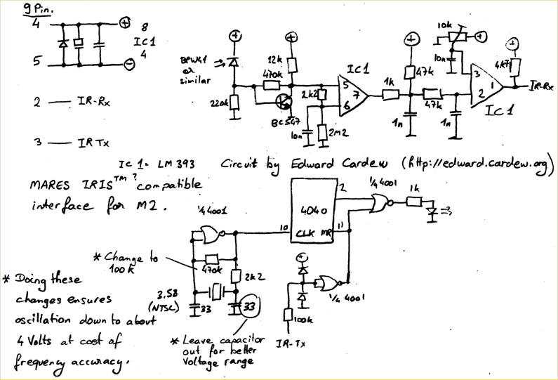
A TSOP4156 is often difficult to obtain or expensive to purchase. In response, an individual utilized old BPW41 infrared diodes to construct a custom receiver. The power source is derived from the RS232 port, requiring a minimum of 5.5...
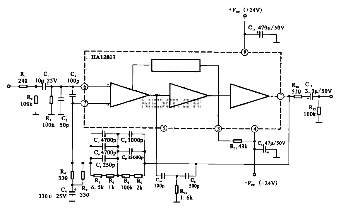
Low-noise preamplifier circuit. This circuit demonstrates a typical low-noise preamplifier design, which can be utilized to amplify signals from sources such as magnetic heads and microphones within audio applications. The input signal is coupled through a capacitor and subsequently...
That circuit protects the overdriven signals going into an amplifier. Instead of a zener diode, we use a transistor. That way we ensure that the above the ordinary input voltages (1 volt r.m.s.) can be achieved without distortion. Also,...
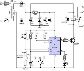
An effective domestic alarm system is most effective when it never activates, and the best way to achieve this is to create the illusion that the premises are occupied. Most burglaries are committed by petty thieves who seek simplicity...
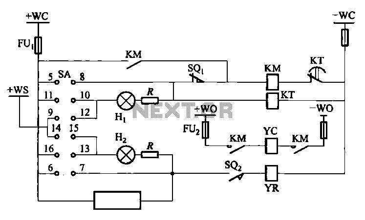
The DW10M de-excitation type switch is based on the DW10 automatic air circuit breaker, transitioning from normally open to normally closed contact. The models available include DW10M-200, DW10M-400, and DW10M-600. The control circuit for this type switch is illustrated...
All sound effects are generated internally by the HT2884 integrated circuit (IC). The device operates on a 3-volt battery but is compatible with any voltage ranging from 2.5 to 5 volts. Switch S1 functions as the on/off switch. The...