
EMEM2 and EMEM3D frequency device construction and operation

The EMEM2 circuit design incorporates a variety of components that work in tandem to create a functional device capable of generating a specific frequency range. The six potentiometers allow for precise tuning of the output frequency, essential for achieving the desired therapeutic effects. The inclusion of adjustable ballast resistors enhances the flexibility of the power settings, enabling users to modify the output according to their requirements.
The device's structural integrity is ensured through the use of sturdy 1x6 lumber for the shelves and supports, which not only provides a robust framework but also facilitates effective heat dissipation from the components housed within. The careful arrangement of components, including the ignition coil and transistor, minimizes interference and optimizes performance.
Safety features are paramount, particularly given the high voltages involved in the operation of this device. The design includes physical barriers to prevent accidental contact with high voltage areas, and the enclosure is designed to accommodate foam padding, further enhancing user safety. The strategic placement of components, such as the fan and heat sink, ensures adequate cooling and efficient operation.
Overall, the EMEM2 represents a sophisticated approach to frequency generation for therapeutic applications, combining practical design considerations with advanced electronic principles. The device serves as a research tool, providing insights into the potential benefits of frequency therapy while emphasizing the importance of safety and proper handling.The EMEM2 was invented by Dan Tracy. In a conversation with "Doug", the inventor of the large coil device, he commented that the EMEM2 does kill Lyme disease and that it is a lot of machine for the money. It has also been demonstrated to be useful for many other conditions. This version uses 6 pots to give a frequency range of about 7Hz to 10KHz a nd finer tuning in the important 2, 000Hz range. Bruce Stenulson`s ideas of having a set/run switch and having adjustable ballast resistors are incorporated. The adjustable ballast is handier than my old clip lead method! For simplicity of construction and economy I have put the resistors in series instead of using a separate one for each power setting.
Instructions for a contact/radiant version and then modifications for a pure radiant EMEM3 version are given. Warning: Very high voltages are involved. If you are not familiar with the safety procedures required, please do not try any of this. Also, in view of the current lawsuit lunacy, it needs to be pointed out that this device has not been approved for use on humans.
It probably should not be used near those with heart pacers or irregular heart rate. It is a research device only that you use at your own risk. The frame or box consists of 3 shelves which are pieces of 1X6 lumber. The top and bottom shelves are 2" longer than the tube, and the middle shelf is 1/2" longer than the tube, allowing 1/4" space on each end of the tube. These shelves are held together by 2 1X6 upright end pieces that are 10" long. So the whole thing looks like a small 3 shelf book case. The size of the power supply and the length of the tube determine the size of the box needed to house the unit.
There is a 4-3/4" space between the top and middle shelves, and a 4-1/2" space between the middle and bottom shelves. Between the bottom and middle shelf is a 4-1/2" space where the tube goes. The tube has usually been in the bottom area for reasons of comfort if one wants to rest their arms on a table and wrap fingers around the tube.
It could just as easily be put in the top area if desired, though the frequency may be easier to set if the pots are on top and the tube below. The tube is supported by three 4-1/2 inch long upright 1X6 supports which go between the shelves. One is in the center, and one is 2" from left end - that is, there is a 2" space between the support and the end piece.
The right support can be 2-3" from the right end piece to leave room for ballast resistors. The supports also serve to keep fingers away from high voltage at the ends of the tube. 1-1/2" holes for the tube are drilled though the 3 tube supports. The holes are centered up and down, and the hole centers are 2" from the front. There is room for foam padding around the tube at each hole. The middle shelf has the ignition coil, the Darlington 2N6059 transistor, the 555 timer board, and the power supply. The coil is mounted in the back left corner with the "business end" facing left. The tip of the spark plug is about 1/4" or so from the end support. A hole is drilled in the middle shelf below the end of the coil for the wire from the spark plug to the tube.
In front of the coil on the far left (1-1/4" or so from the upright) is the transistor and its 2-1/4 by 2-1/2 by 1-1/2 inch thick heat sink. A smaller heat sink can be used with this version if desired as the transistor stays cooler than with previous models.
The heat sink lays on its side with the contacts on the right. It can be held in place by a strap consisting of a heavy solid copper wire and 2 wood screws. The 2 inch square 555 timer board is mounted on 1/4" spacers to the right of the heat sink. It may be desirable to move the 555 board as far as convenient to the right to keep it farther from the spark gap. Above the transistor, under the top shelf is a 12 volt 3" muffin fan. The fan is mounted on 3/4" spacers to space it away from the top shelf. The plugs cu 🔗 External reference
Related Circuits
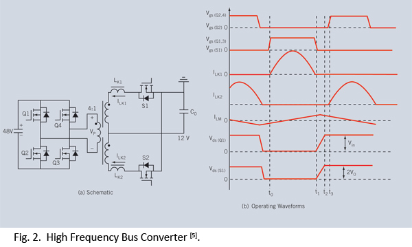
Distributed power systems are commonly used in telecommunications, networking, and high-end server applications, utilizing a 48 V bus voltage derived from the telecom industry. This 48 V bus supplies several isolated point-of-load (POL) converters that power the end loads,...
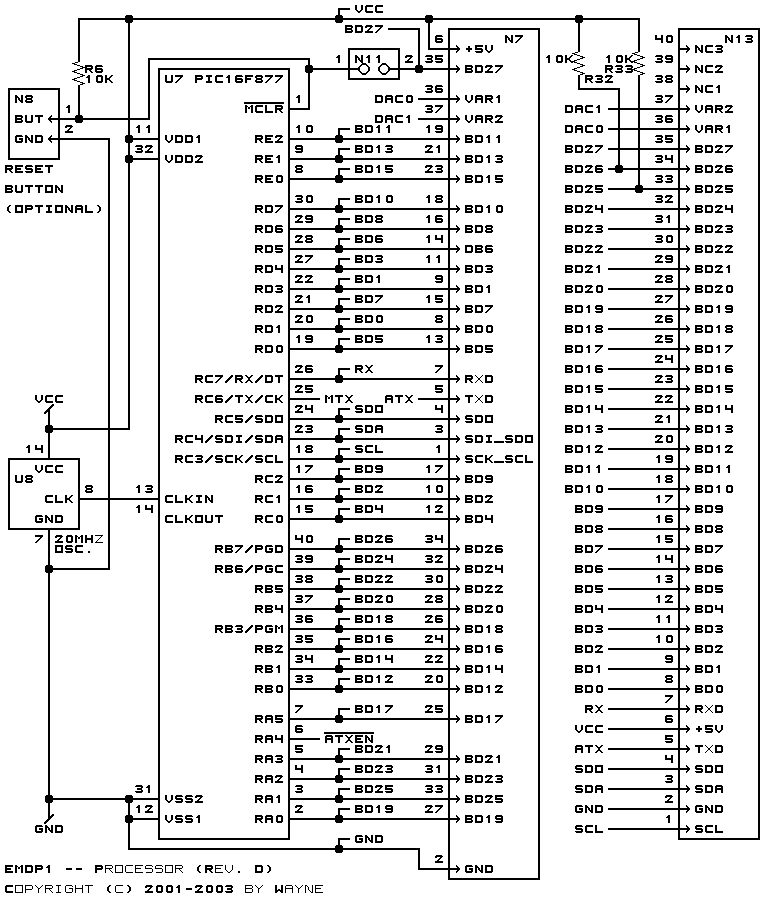
The power supply derives its energy from a 24-volt VDC wall adapter, which can be connected through N1, an onboard connector, or N10, an off-board connector. The power switch can be mounted either on the board or off-board via...

It has been determined that the Hijack method for obtaining serial data from the Mindflex to the iPhone will likely not be utilized. This decision is primarily based on the availability of most components needed to construct a similar...
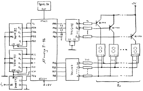
In counter mode, it provides 1 Hz resolution up to 100 MHz. In timer mode, the maximum resolution is 0.0000001 Hz up to 1 Hz. The resolution decreases by one digit for each additional decade. Multiple frequency updates per...
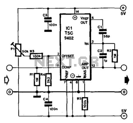
Teledyne Semiconductor's Type TSC9402 is a versatile integrated circuit (IC) capable of converting voltage to frequency and frequency to voltage. It is well-suited for use as an add-on unit for measuring frequencies with a multimeter, requiring only a few...
This PIC software integrates frequency counter and frequency locking functions. By incorporating a couple of transistors and an operational amplifier (TL082), it is feasible to stabilize the LC oscillator frequency. The frequency reference is established from the measured frequency...