
Frequency Counter and Timer

The circuit described offers a versatile frequency counter and timer functionality, with a resolution that is adaptable depending on the operational mode. In counter mode, the device is capable of handling frequencies up to 100 MHz while maintaining a 1 Hz resolution, making it suitable for high-speed applications. Conversely, in timer mode, the resolution is significantly enhanced, allowing for measurements as precise as 0.0000001 Hz, albeit limited to frequencies up to 1 Hz.
The implementation of a sliding window calculation method allows the device to update its frequency readings multiple times per second, enhancing responsiveness. This feature is particularly beneficial in applications where frequency stability and quick response times are critical.
For in-circuit programmability of the AVR microcontroller, careful consideration of the circuit design is necessary. The use of 47 kΩ resistors to isolate third-party programming connections is a prudent design choice that minimizes interference and protects the integrity of the programming signals. The combination of these resistors with the Mega8 gate capacitance forms a low-pass filter that helps to stabilize the signals during programming, ensuring reliable operation.
Software compensation for settling time is employed to further enhance performance, allowing the external counter to operate effectively despite any potential delays introduced by the circuit.
The test board assembly, as depicted in the accompanying image, showcases the complete counter circuit, with the exception of the 7-segment display components, which are housed on a separate board for ease of integration. The connections for digit selection and 7-segment code transmission are clearly defined, facilitating straightforward assembly and troubleshooting.
This final board design is optimized for integration into the intended device, featuring dedicated connectors for power supply, 7-segment display code, digit selection, in-circuit programming, and TTL signal input. This comprehensive approach ensures that the circuit is both functional and adaptable, meeting the demands of various electronic applications.In counter mode it provides 1Hz resolution up to 100Mhz. In timer mode maximum resolution is 0. 0000001 Hz up to 1Hz. Resolution is reduced by one digit for each additional decade. Multiple frequency updates per second by employing a sliding window for calculation. In case the AVR should be programmable in circuit, a few modifications must be made. In essence all third parties on wires used for programming are isolated using 47k resistors. The resistors in combination with Mega8 gate capacity create a low pass. This is software compensated using increased settling time for the external counter. This picture shows the test board with the full counter circuit except the 7 segment LEDs. Those are already mounted and soldered on a separate board. The wires on the top right connect to it. (One connector for digit selection and one for the actual 7 segment code. ) This is the final board that will be put into the device. It has connectors for power, 7 segment code, digit selection, in circuit programming and TTL signal input. 🔗 External reference
Related Circuits
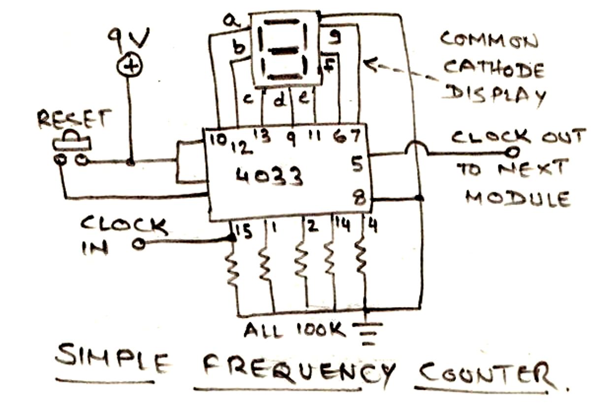
The circuit illustrated below is designed for measuring frequency in Hertz (Hz). It is straightforward to construct, utilizing a single IC 4033 and a common cathode display as the main components. For measuring higher frequencies, typically in the range...
This circuit was developed in response to requests from visitors for a timer that can emit a beep after intervals of one, two, three minutes, and so forth, suitable for jogging purposes. As illustrated in the circuit diagram, SW1...
The electronic counter of the winding machine utilizes an LED digital display to indicate the number of turns of the wound coil, with a maximum counting capacity of 9900 turns. The operational principle of the winding machine circuit consists...
Inquiry regarding the circuit design involving ICs 4029N and 4511N, specifically questioning whether these components function as a driver/decoder. The datasheet was consulted but did not provide precise specifications. The IC 4029N is a binary up/down counter that can count...
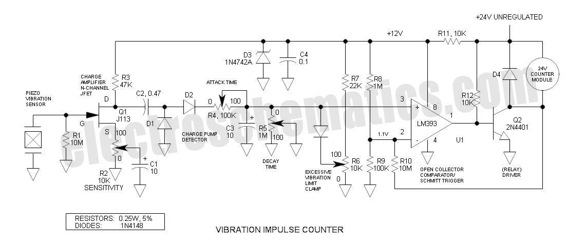
This is an adaptation of the previously posted bicycle anti-theft alarm. A commenter expressed interest in modifying it for use with a threshold step plate vibration detector. The adaptation of a bicycle anti-theft alarm into a threshold step plate vibration...
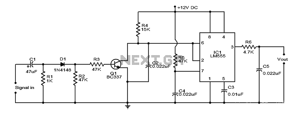
This document provides an overview of a simple circuit diagram for frequency (F and V) voltage conversion. It describes a digital frequency meter circuit primarily based on the LM555 timer IC, which is commonly used in various applications, including...